Table of Contents
Advertisement
Available languages
Available languages
Quick Links
1003105.AB draft
ENGLISH - FRANÇAIS
Bumblebee Installation Instruction /
Statement of Conformity
BUMBLEBEE
Wireless pressure and temperature sensors for
potentially explosive atmospheres
Capteur de pression et de température sans fil pour
atmosphères potentiellement explosives
Installation instructions
Instructions d'installation
Please keep this manual with the Bumblebee device
Il est recommandé de garder ce manuel avec l'appareil Bumblebee
0459
1
12/2022
Advertisement
Table of Contents

Summary of Contents for SRETT BUMBLEBEE
- Page 1 Wireless pressure and temperature sensors for potentially explosive atmospheres Capteur de pression et de température sans fil pour atmosphères potentiellement explosives Installation instructions Instructions d’installation Please keep this manual with the Bumblebee device Il est recommandé de garder ce manuel avec l’appareil Bumblebee 0459 12/2022...
- Page 2 1003105.AB draft ENGLISH - FRANÇAIS Bumblebee Installation Instruction / Statement of Conformity Bumblebee Installation Instruction English Version: page 3 Version Française: page 28 Declaration of conformity page 54 PED: page 61 12/2022...
- Page 3 1003105.AB draft ENGLISH - FRANÇAIS Bumblebee Installation Instruction / Statement of Conformity ENGLISH VERSION 12/2022...
-
Page 4: Table Of Contents
1003105.AB draft ENGLISH - FRANÇAIS Bumblebee Installation Instruction / Statement of Conformity Contents 1. GENERAL INFORMATION ................. 8 1.1. U SAGE AND APPLICATIONS 1.2. FCC N OTICE 1.3. I NSTALLATION AND SERVICING 1.4. D EVICE DESCRIPTION 1.5. T HEORY OF OPERATIONS 1.6. - Page 5 1003105.AB draft ENGLISH - FRANÇAIS Bumblebee Installation Instruction / Statement of Conformity 6. ADVANCED OPERATIONS ................22 6.1. D ATA RECORDS 6.1.1. ROVISIONING THE DEVICE ONTO THE NETWORK 6.1.2. ETWORK COVERAGE IN THE DEPLOYMENT ZONE ’ 6.1.3. PPLICATIVE UPLINK TRANSMISSION AT DEVICE S INITIATIVE 6.1.3.1.
- Page 6 1003105.AB draft ENGLISH - FRANÇAIS Bumblebee Installation Instruction / Statement of Conformity 2.3. E NVIRONNEMENT 2.4. B ATTERIE ET AUTONOMIE 2.5. O PÉRATIONS 2.6. M ESURE DE LA PRESSION 2.7. M ESURE DE LA TEMPÉRATURE 2.8. C OMMUNICATION SANS FIL 3.
- Page 7 1003105.AB draft ENGLISH - FRANÇAIS Bumblebee Installation Instruction / Statement of Conformity 6.3.5. ÉLÉCHARGEMENT D AMORÇAGE 7. STOCKAGE ....................... 52 8. RÉPARATION ....................53 9. RECYCLAGE ..................... 53 10. SERVICE CLIENT....................53 12/2022...
-
Page 8: General Information
1003105.AB draft ENGLISH - FRANÇAIS Bumblebee Installation Instruction / Statement of Conformity 1. GENERAL INFORMATION 1.1. Usage and applications ● ARNING ISK TO LIFE OR PROPERTIES Perform a whole system risk assessment before using this product for any application involving serious risks to life or property. -
Page 9: Installation And Servicing
1003105.AB draft ENGLISH - FRANÇAIS Bumblebee Installation Instruction / Statement of Conformity • Radiation Exposure Statement: This equipment complies with FCC radiation exposure limits set forth for an uncontrolled environment. This equipment should be installed and operated with minimum distance 20 cm (7.87 in) between the radiator and your body. -
Page 10: Device Description
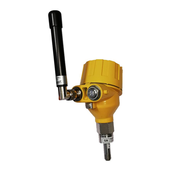
Ground Screw: For safety purposes, the Bumblebee device shall be connected to earth ground. 1.5. Theory of operations The Bumblebee sensor periodically acquires pressure or temperature data, records them in its internal memory, and transmits them wirelessly. Data records are time stamped, thanks to an internal clock. -
Page 11: Integration Of Bumblebee In An Iot System
1.6. Integration of Bumblebee in an IoT system Bumblebee should be deployed within an IoT (Internet of Things) system comprising an LoRaWAN wireless network that covers the location where the device is deployed. An Information system is needed to make use of the data transmitted by the device via LoRaWAN. -
Page 12: Operation In Explosive Atmospheres
Bumblebee Installation Instruction / Statement of Conformity 1.8. Operation in explosive atmospheres Bumblebee device is certified by LCIE with the number 19 ATEX 3003 X. The complete marking is: 0081: II 1/2 G Ex ia IIC T4 Ga/Gb. Symbol definition LCIE N°: 19... -
Page 13: Label Us Market
1003105.AB draft ENGLISH - FRANÇAIS Bumblebee Installation Instruction / Statement of Conformity 1.9.2. Label US market 1.9.3. Symbols used for the label Protected from dust and powerful jets Read the manual IP66 of water Electronic equipment subject Name address selective... -
Page 14: Specifications
1003105.AB draft ENGLISH - FRANÇAIS Bumblebee Installation Instruction / Statement of Conformity 2. SPECIFICATIONS 2.1. External dimensions with ANH42 antenna Without ½ NPT Connection 2.2. Housing Weight (including battery) 1.3 kg Material Aluminum with epoxy paint. Protection class IP66 2.3. Environment Operating temperature range for safe operation in -20°C to 55°C... -
Page 15: Operations
1003105.AB draft ENGLISH - FRANÇAIS Bumblebee Installation Instruction / Statement of Conformity Lost of autonomy per year in deactivated mode 2.5. Operations Minimum acquisition period 5 min Acquisition period by default Time keeping accuracy 20 minutes/year maximum drift Size of internal memory for measurement records 10 years, FIFO 2.6. -
Page 16: Product Installation
(antenna pointing upward). Go through Procedure B (see section 3.7). You may also use the Bumblebee mobile app to check LoRa signal to ratio (see section 6.3.1). Other antennas or remote antenna may be used if the system associating antenna and device compies with EN 60079-25... -
Page 17: Mechanical Installation
32 mm open-end wrench, and one 32 mm open-end wrench Procedure duration (estimated): 15 minutes 3.3.1.1. Description of the pressure fitting assembly Bumblebee is connected to the process equipment through a pressure fitting assembly which is in two steps : ● A coupling compatible with Autoclave Engineers® SF562CX . -
Page 18: Mechanical Installation Of Bumblebee Temperature Sensor
Step 1. Lubricate male threads of Gland with a metal based thread lubricant. Slip Gland on Bumblebee nose. Screw Thread Collar on Bumblebee Nose until one to two threads are exposed between collar and cone. Note that the thread is left handed. -
Page 19: Installing Antenna
3.5. Connecting Bumblebee to the ground The Bumblebee device needs to be connected to ground potential. If the connection is not properly insured through the pressure fitting, this function is performed by connecting the ground screw (see figure 1) to a terminal to the earth ground. -
Page 20: Procedure B. Bumblebee Activation, Reboot And Connectivity Test
LoRaWAN network Procedure B again The device is delivered deactivate. After activation, it remains active until it is deactivated by using the Bumblebee mobile app. By rebooting, the device restarts periodic acquisition acquisition. Subsequent dates and times at which measurements are acquired, are modified accordingly. -
Page 21: Maintenance Operations
Step 1. Unlock the the lid locking screw (see figure 1) Step 2. Unscrew the removable lid. (see figure 1) Step 3. Remove the battery one at a time to keep the bumblebee active. Battery holders are tight, you may use a flat screwdriver as a lever Step 4. -
Page 22: Advanced Operations
Uplink messages are the combination of one byte ASCII code, hereafter denominated “Message Port” and a payload.The Message port defines what type of payload is in the message. Bumblebee device transmits, at its initiative, three types of payload, shown in the table below. using little endian bits order. -
Page 23: Mini New Data Message Description, Port
1003105.AB draft ENGLISH - FRANÇAIS Bumblebee Installation Instruction / Statement of Conformity Message port Mesagg Payload 1byte ACSII Occurence Version firmware e type description code Sent each time the device join a new Section Up to version 73 (‘I’) Info network. -
Page 24: Data Messages Type K (Port 75) (From Firmware Version 3.0.X)
1003105.AB draft ENGLISH - FRANÇAIS Bumblebee Installation Instruction / Statement of Conformity Status Uint8_t Status of the device (see below) Reserved uint8_t 6.1.3.5. New data message description, Port 78 (up to firmware version 2.x.x) Data Type Bumblebee Pressure Bumblebee sensor... -
Page 25: Status Byte Description
6.2.1. Low battery indicator Bumblebee provides, in the Status Byte (see section 6.1.3.7) an indicator of battery end of life. The indicator is transmitted on every LoRa message when more than 95% of the battery capacity has been used. When this indicator appears, the battery should be replaced immediately ! Batteries used are Lithium Thionyl Chloride batteries and provide very little indications regarding their depletion. -
Page 26: Managing Battery Levels
● Bumblebee mobile app works on Android mobile devices. ● Bumblebee mobile app communicates to the device via BLE and provides multiple information (ref to section 6.3.1 to 6.3.5 ● Bumblebee mobile app allows the configuration, the location, and gather records of Bumblebee devices. -
Page 27: Other Information Relative To The Device
7. STORAGE After a short press, if the LED stays on for a long time, it does not mean that the Bumblebee is awake. This means that the BBB is activated and it may be trying to connect to the network or is performing data acquisition. - Page 28 1003105.AB draft ENGLISH - FRANÇAIS Bumblebee Installation Instruction / Statement of Conformity VERSION FRANÇAISE 12/2022...
- Page 29 1003105.AB draft ENGLISH - FRANÇAIS Bumblebee Installation Instruction / Statement of Conformity TABLE DES MATIERES 1. GENERAL INFORMATION ................. 8 1.1. U SAGE AND APPLICATIONS 1.2. FCC N OTICE 1.3. I NSTALLATION AND SERVICING 1.4. D EVICE DESCRIPTION 1.5. T HEORY OF OPERATIONS 1.6.
- Page 30 1003105.AB draft ENGLISH - FRANÇAIS Bumblebee Installation Instruction / Statement of Conformity 6.1. D ATA RECORDS 6.1.1. ROVISIONING THE DEVICE ONTO THE NETWORK 6.1.2. ETWORK COVERAGE IN THE DEPLOYMENT ZONE ’ 6.1.3. PPLICATIVE UPLINK TRANSMISSION AT DEVICE S INITIATIVE 6.1.3.1.
- Page 31 1003105.AB draft ENGLISH - FRANÇAIS Bumblebee Installation Instruction / Statement of Conformity 2.4. B ATTERIE ET AUTONOMIE 2.5. O PÉRATIONS 2.6. M ESURE DE LA PRESSION 2.7. M ESURE DE LA TEMPÉRATURE 2.8. C OMMUNICATION SANS FIL 3. INSTALLATION DU PRODUIT ................41 ’...
- Page 32 1003105.AB draft ENGLISH - FRANÇAIS Bumblebee Installation Instruction / Statement of Conformity 7. STOCKAGE ....................... 52 8. RÉPARATION ....................53 9. RECYCLAGE ..................... 53 10. SERVICE CLIENT....................53 12/2022...
-
Page 33: Informations Générales
1003105.AB draft ENGLISH - FRANÇAIS Bumblebee Installation Instruction / Statement of Conformity 1. INFORMATIONS GÉNÉRALES 1.1. Utilisation et applications ● VERTISSEMENT RISQUE POUR LA VIE OU LES BIENS Effectuer une évaluation des risques de l’ensemble du système avant d’utiliser ce produit pour toute application impliquant des risques graves pour la vie ou les biens. -
Page 34: Installation Et Entretien
Bumblebee communique via un réseau sans fil LoRaWAN. Le capteur de température Bumblebee est basé sur une thermistance de platine. Le capteur de pression Bumblebee est basé sur un capteur de pression piézo-résistif à compensation de température. Figure 1. Pression du Bumblebee (à gauche) et capteur de température (à droite) Bouton LED: Le bouton LED permet l’interaction avec l’utilisateur. -
Page 35: Théorie Des Opérations
Vis de verrouillage: Le couvercle amovible peut être verrouillé sur le corps. Ceci est nécessaire si le produit vibre. Vis de mise à la terre: Pour des raisons de sécurité, le dispositif Bumblebee doit être connecté à la terre. 1.5. Théorie des opérations Le capteur Bumblebee acquiert périodiquement des données de pression ou de température, les enregistre... -
Page 36: Réglementations Européennes Appliquées
● 1907/2006 REACH (Enregistrement, évaluation, autorisation et restriction des substances chimiques) ● 2014/30/EU CEM (Compatibilité électromagnétique) 1.8. Fonctionnement en atmosphères explosives L’appareil Bumblebee est certifié par LCIE sous le numéro 19 ATEX 3003 X. Le marquage complet est le suit: 0081: II 1/2 G Ex ia IIC T4 Ga/Gb. -
Page 37: Étiquetage Des Produits
1003105.AB draft ENGLISH - FRANÇAIS Bumblebee Installation Instruction / Statement of Conformity 1.9. Étiquetage des produits 1.9.1. Etiquette ATEX / IECEX / UKCA 1.9.2. Etiquette US (Marché américain) 12/2022... -
Page 38: Étiquette
1003105.AB draft ENGLISH - FRANÇAIS Bumblebee Installation Instruction / Statement of Conformity 1.9.3. Symboles utilisés pour l’étiquette Protégé de la poussière et des Lire le manuel IP66 puissants jets d’eau Équipements électroniques soumis à Nom et adresse du fabricant des installations de collecte sélective pour la récupération et le recyclage... -
Page 39: Spécifications
1003105.AB draft ENGLISH - FRANÇAIS Bumblebee Installation Instruction / Statement of Conformity 2. SPÉCIFICATIONS 2.1. Dimensions externes avec antenne ANH42 Dimensions Sans Raccord ½ NPT 2.2. Boitier Poids (y compris la batterie) 1,3 kg matériel Aluminium avec peinture époxy. Classe de protection IP66 2.3. -
Page 40: Opérations
1003105.AB draft ENGLISH - FRANÇAIS Bumblebee Installation Instruction / Statement of Conformity Durée de conservation du produit avant l’activation s’il 3 ans est conservé en dessous de 30 °C Autonomie pour une période d’acquisition de 5 minutes 1,5 ans Autonomie pour une période d’acquisition de 10 minutes 2,5 ans Autonomie pour une période d’acquisition de 15 minutes... -
Page 41: Installation Du Produit
P/N 1001920 ou T********2 : capteur de température -60°C à +200°C iv. L’équipement est alimenté par deux cellules SAFT LS 14500, 3,6V. v. Lors de l’utilisation d’une antenne de type ANH42 ou ANH52 fournie par SRETT [1], elle doit être installée dans la zone 1 GB EPL ou supérieure. -
Page 42: Installation Mécanique
Étape 1. Lubrifier les fils mâles de Gland avec un lubrifiant de fil à base de métal. Slip Gland sur le nez de Bumblebee. Collier de filetage à vis sur le nez de Bumblebee jusqu’à ce qu’un à deux filets soient exposés entre le collier et le cône. Notez que le thread est gaucher. -
Page 43: Installation Mecanique Du Capteur De Temperature Bumblebee
Durée de la procédure:30 minutes Le capteur de température Bumblebee est destiné à être utilisé avec un puits thermique, voir figure 5. Étape 1. Fixez le connecteur de processus de l’extension inférieure au puits thermique à l’aide d’une clé à bout ouvert de 27 mm (Figure 5 gauche). -
Page 44: Installation De Lantenne
3.5. Connexion du Bumblebee au sol L’appareil Bumblebee doit être connecté au potentiel de masse. Si la connexion n’est pas correctement assurée par le raccord de pression, cette fonction est assurée en reliant la vis de mise à terre (voir figure 1) à une borne à... -
Page 45: Procedure B. Activation Du Bumblebee , Redemarrage Et Test De Connectivite
S'il n'y a toujours pas de signal LED avec la nouvelle batterie, contactez le service après-vente. 3.7.2. Procédure B. Activation du Bumblebee, redémarrage et test de connectivité La procédure B peut être effectuée à tout moment, elle déclenche les opérations suivantes : ●... -
Page 46: Opérations De Maintenance
Étape 1. Déverrouillez la vis de verrouillage du couvercle (voir figure 1). Étape 2. Dévissez le couvercle amovible (voir figure 1). Étape 3. Retirez les batteries l’une après l’autre pour garder le bumblebee actif. Les supports de batterie sont serrés, vous pouvez utiliser un tournevis plat comme levier. -
Page 47: Provisionnement De L ' Appareil Sur Le Reseau
● L’APPEUI : L'APPEUI est 8C-19-2D-70-00-07-00-00. Elle est publique et définit l'application Bumblebee. 6.1.2. Couverture réseau dans la zone de déploiement Le dispositif ne peut communiquer que si le réseau LoRa couvre le lieu précis où il est déployé. -
Page 48: Du Micrologiciel )
Température en °C Température Int_8_t Température in °C Température in °C Statut Uint8_t Etat de l'appareil (voir ci-dessous) Réservé uint8_t Type de données Capteur de pression Bumblebee Capteur de température Bumblebee Timestamp uint32_t Horodatage des données Horodatage des données 12/2022... -
Page 49: Description Du Nouveau Message De Donnees , Port
1003105.AB draft ENGLISH - FRANÇAIS Bumblebee Installation Instruction / Statement of Conformity Données float_t Pression en Barg Température en °C Température Int_8_t Température en °C Température en °C Status Uint8_t Etat de l'appareil (voir ci-dessous) NA Réservé uint8_t NA NA 6.1.3.5. -
Page 50: Description De L'octet D'état
1003105.AB draft ENGLISH - FRANÇAIS Bumblebee Installation Instruction / Statement of Conformity Info Port de Info Port de Info Port de message message de message message de message message de port données port données port données 0x78 (‘N’) 0x74 (‘J’) 0x73 (‘I’) -
Page 51: Gestion Du Niveau De La Batterie
à leur épuisement. Par conséquent, cet indicateur n'est pas un indicateur fiable pour gérer le remplacement des batteries sur le terrain. SRETT recommande de gérer le niveau de la batterie en se basant sur le compteur de consommation actuel comme présenté ci-dessous. -
Page 52: Téléchargement Des Enregistrements De Données
1003105.AB draft ENGLISH - FRANÇAIS Bumblebee Installation Instruction / Statement of Conformity Date et heure d'acquisition de cette valeur Affichage de la dernière mesure acquise. Indicateur de batterie Inicateur visible Si environ 95% de la capacité de la batterie a été... - Page 53 SERVICE CLIENT Pour contacter le service clientèle, veuillez envoyer un e-mail à l'adresse suivante : support@srett.com. Vous pouvez également contacter le service client SRETT directement par téléphone au +33 146 103 110 (du lundi au vendredi de 10h00 à 17h00 CET).
- Page 54 1003105.AB draft ENGLISH - FRANÇAIS Bumblebee Installation Instruction / Statement of Conformity DÉCLARATION UE DE CONFORMITÉ EU STATEMENT OF CONFORMITY 12/2022...
- Page 55 1003105.AB draft ENGLISH - FRANÇAIS Bumblebee Installation Instruction / Statement of Conformity 12/2022...
- Page 56 Annex A to the EU statement of Conformity Directive 2011/65/UE - LUSD (2) Directive 2011/65/EU – ROHS (2) Tous les modèles de capteur de pression/température électroniques des séries Bumblebee sont conformes à la norme harmonisée : All models of electronic pressure/temperature sensor bumblebee series are in accordance with the harmonized standard: Documentation technique pour l’évaluation des produits électriques et électroniques...
- Page 57 Annex B to the EU statement of Conformity Directive 2014/30/UE - CEM Directive 2014/30/EU – EMC Les capteurs de pression/température des séries Bumblebee qui par construction incorporent des composants électroniques satisfont aux essais d’immunité ou d’émission aux prescriptions de la directive de compatibilité...
- Page 58 Annex C to the EU statement of Conformity Directive 2014/53/UE - RED Directive 2014/53/EU – DER Les capteurs de pression/température type Bumblebee qui par construction incorporent un équipement radio satisfont aux essais conforme à la directive The Bumblebee pressure/temperature sensors of our fabrications incorporating radio equipment meet the requirements of the Directive La conception de ces matériels répond aux normes suivantes :...
- Page 59 Annexe D à la déclaration UE de conformité Annex D to the EU statement of Conformity Directive 2014/34/UE - ATEX Directive 2014/34/EU – ATEX Les capteurs de pression/température type Bumblebee sont disponibles avec un ou plusieurs types d’approbations pour une utilisation en atmosphères explosibles :...
- Page 60 Tous les modèles de capteur de pression/température électroniques des séries Bumblebee sont conformes à un indice de protection IP66. All models of electronic pressure/temperature sensor bumblebee series are comply with the IP66 degree protection. L’installateur et l’utilisateur doivent cependant observer les prescriptions de montage et de raccordement définies dans nos catalogues, notices techniques.
- Page 61 1003105.AB draft ENGLISH - FRANÇAIS Bumblebee Installation Instruction / Statement of Conformity DÉCLARATION DEP DE CONFORMITÉ PED STATEMENT OF CONFORMITY Déclaration de conformité aux exigences de performances essentielles de l’annexe I de la directive PED 2014/68/EU Relative aux Équipements Sous Pression...
- Page 62 1003105.AB draft ENGLISH - FRANÇAIS Bumblebee Installation Instruction / Statement of Conformity 12/2022...
Need help?
Do you have a question about the BUMBLEBEE and is the answer not in the manual?
Questions and answers