
Related Manuals for Atlas Copco Focus 61

Summary of Contents for Atlas Copco Focus 61
- Page 1 User Guide Focus 61 Atlas Copco Industrial Technique AB 9839 0211 01 2020-04 Edition 2.0...
- Page 2 Focus 61 Display updated (par. 4.1), Focus 60 (Decommissioned) / Focus 61 Ethernet Ports updated (par. 4.4), Focus 60 (Decommissioned) / Focus 61 Barcode Scanner Interface (RS232) updated (par. 4.5), Focus 60 (Decommissioned) / Focus 61 I/O BUS (CAN) updated (par.
- Page 3 (chapter 11) Installing Focus 60 (Decommissioned) / Focus 61 updated (par. 3.1), Focus 60 (Decommissioned) / Focus 61 Ethernet Ports updated (par. 4.4), Focus 60 (Decomissioned) / Focus 61 SD cards added (par. 4.8), Associating the MWR with Station(s) updated 30 October (par.
- Page 4 (par. 6.3). Copyright Atlas Copco Industrial Technique AB NOTE: This User Guide may be altered without further notice. For further information log on to the Atlas Copco website: www.atlascopco.com NOTE: The programming software (ToolsTalk BLM) may be updated with no changes regarding the Focus 61 functionalities.
-
Page 5: Table Of Contents
WORKING WITH ToolsTalk BLM .................. 29 Installing the software..................... 30 Registering the software ..................30 Upgrading the software ..................31 Connecting with the Focus 61 ................31 5.4.1 Menu bar ........................34 5.4.1.1 Enabling LOG Viewer ................34 5.4.1.2 Downloading LOG file(s) ................34 5.4.1.3 ToolsTalk BLM Backup and Restore / Update .......... - Page 6 Table of Contents Focus 61 User Guide 6.3.1 Pset parameters settings - Strategy ................ 55 6.3.2 Pset parameters settings - Torque Limits ..............57 6.3.3 Pset parameters settings - Angle Limits ..............59 6.3.4 Pset parameters settings - Other settings ............... 59 Configuring Job ......................
-
Page 7: Acronyms And Abbreviation
Mechatronic wrench – torque and angle: both torque and angle can MWR- TA be measured. Pset Parameters setting of the tightening. Assembly of: Focus 61, MWR, cradle and PC with installed System ToolsTalk BLM. 7 (118) 9839 0211 01 Edition 2.0... -
Page 8: Introduction
Introduction Focus 61 User Guide 1 INTRODUCTION About this Document This document is a User Guide for the Focus 61: it consists of the following main parts: Part Name Description This chapter introduces this User Guide and provides the Chapter 1 Introduction technical specifications for the Focus 61. -
Page 9: Specifications
Focus 61 User Guide Introduction Part Name Description Atlas Open Protocol This appendix lists the Atlas Open Protocols available for Appendix A (AOP) the Focus 61. Appendix B Error code AOP This appendix lists the error code sent in MID 0071. - Page 10 Introduction Focus 61 User Guide DIMENSIONS The unit of the dimensions is in mm. INTERFACES • Ethernet ports • Barcode Scanner interface (RS232) • I / O BUS (CAN) • Wave Flexible Antenna connector • Digital output • Radio module frequencies: WARNING: Refer to the local Regulatory Domain for frequency selection.
- Page 11 Focus 61 User Guide Introduction Country Number Channel Frequency [MHz] Data rate [bit/s] 869.006 38400 869.573 38400 869.840 38400 868.034 19200 868.297 19200 868.502 19200 868.706 19200 869.006 19200 869.573 19200 869.840 19200 902.791 38400 906.478 38400 907.004 38400 910.691 38400 912.271...
- Page 12 Introduction Focus 61 User Guide Country Number Channel Frequency [MHz] Data rate [bit/s] 919.900 38400 920.500 38400 921.100 38400 922.500 38400 923.100 38400 917.300 19200 918.900 19200 919.900 19200 920.500 19200 921.100 19200 922.500 19200 923.100 19200 922.800 38400 923.400 38400 923.600...
- Page 13 40 °C (104 °F) • Altitude: Up to 2000 m REQUIREMENTS TO INSTALL ToolsTalk BLM Below are the PC minimum requirements for installation of Focus 61 Management Software (ToolsTalk BLM): • Processor: 800 MHz or above •...
-
Page 14: System Overview
The Focus 61 is a controller designed to manage a production line station where mechatronic wrenches (MWR) are used to do documented tightening operations. The Focus 61 can manage up to 10 MWR divided into two stations. On each station, one MWR can be active at the same time. - Page 15 Focus 61 User Guide System Overview Below are the main functions of Focus 61: MAIN FUNCTIONS FOCUS 61 MWR management via 868 / 915 MHz radio module Torque/Angle/Time monitoring (according to the MWR model) to control if the tightening is OK or Not OK...
-
Page 16: Installation Instructions
Dimensions to define how to install the M5 screws. M5 screw housing NOTE: Use ONLY the power cable provided with the Focus 61 package. The use of any other power cable may impair the protection provided by the equipment. 9839 0211 01 Edition 2.0... - Page 17 Focus 61 User Guide Installation Instructions 2. Connect the power cable to the multifunctional power socket (refer to the figure on the right). Fuses Holder Multifunctional power socket On/Off switch 3. Connect the power cable to the AC Power. 17 (118)
-
Page 18: User Interfaces
If the MWR is associated with one Station of the Focus 61, but either the batteries level of the MWR is too low or the MWR is out of the range of the Focus 61, the yellow LED points out an ERROR (refer to the paragraph LEDs for further details about LEDs): 9839 0211 01 Edition 2.0... -
Page 19: Keyboard
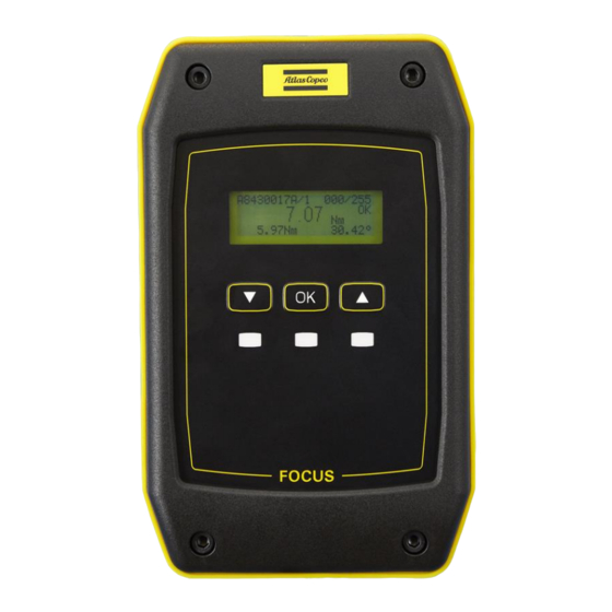
Focus 61 User Guide User interfaces Associate the MWR with a Station of the Focus 61. After few seconds, the Focus 61 shows the data of the ongoing tightening operation on the MWR (refer to the following picture): Batch counter Number of the current tightening over the job step total tightenings. - Page 20 User interfaces Focus 61 User Guide Below is the tree view that shows a hierarchical structure of the Focus 61 menu. Press OK for entering the tree structure. Then press UP and/or DOWN for browsing the Focus 61 menu. config general...
-
Page 21: Leds
=> Exit the time menu back Exit the main menu LEDs There are three LEDs on the Focus 61 front panel. For each LED, different functionalities are indicated: • The Blue LED is on when the system is ready. •... -
Page 22: Ethernet Ports
The Ethernet Port allows the communication between the Focus 61 and ToolsTalk BLM. In addition, this port can be used to receive tightening results via simple TCP/IP data output (Focus 61) or to operate an advanced protocol (e.g. Atlas Open Protocol). -
Page 23: Barcode Scanner Interface (Rs232)
Focus 61 User Guide User interfaces Barcode scanner Interface (RS232) The Focus 61 has a barcode interface RS232 with a switchable 5 V power supply (max 400 mA). The Barcode interface RS232 parameters are: • 8 data bit • 1 stop bit •... - Page 24 User interfaces Focus 61 User Guide • Pin assignment barcode scanner port: PIN # Signal +5 VDC 9839 0211 01 Edition 2.0 24 (118)
-
Page 25: I / O Bus (Can)
User interfaces I / O BUS (CAN) I/O BUS (CAN) (see the pictures below) connects the Stacklight to the Focus 61. The Stacklight is an optional tool that supplies a real-time indication of each tightening result, system status, etc. Furthermore the I/O expander sealed and I/O expander open can be connected to the I/O BUS (CAN). -
Page 26: Wave Flexible Antenna
User interfaces Focus 61 User Guide Wave Flexible Antenna The Wave Flexible Antenna (see the pictures below) allows the Focus 61 to communicate with the MWR. The Wave Flexible Antenna parameters are: • 1/4 Wavelength Whip Antenna • Rugged Flexible Plastic Finish •... -
Page 27: Sd Cards
Focus 61 User Guide User interfaces SD cards The SD cards contain the necessary files for the operating system for the Mainboard (slot 1.1) and the MPC (Slot 2.2). It is possible to read the files saved on the SD card by using the SD card explorer function. -
Page 28: Digital Output
User interfaces Focus 61 User Guide Digital output The Digital output allows to connect lamps or other devices that mange the output signal of the Focus by using the Digital output connector (see the picture below). • Output voltage: 24V •... -
Page 29: Working With Toolstalk Blm
It offers user-friendly programming and real time monitoring. ToolsTalk BLM is a configuration interface between the user and the Focus 61. The main features that characterize the configuration interface between the user and the Focus 61 are as follows: •... -
Page 30: Installing The Software
After installing the software, register at http://softreg1.atlascopco.com/main2.asp?toSoftreg=true; if there is no registration, the software works as demo for 60 days. Once the software is installed, enter the registration form by clicking Start > All Programs > Atlas Copco Tools AB > ACTLicense. -
Page 31: Upgrading The Software
There is no impact through the upgrade on the settings, tightening programs and results. Connecting with the Focus 61 NOTE: This paragraph describes the connection between Focus 61 and ToolsTalk BLM. Click ToolsTalk BLM icon to run the software. After clicking ToolsTalk BLM icon, the following screen opens: 31 (118) 9839 0211 01 Edition 2.0... - Page 32 Then, select the necessary Focus 61. It is also possible to click IP Connection command: it shows the IP Address Connection dialog box which connects a specified Focus 61 with the network. Insert the IP Address of the specified Focus 61 and click Connect.
- Page 33 Focus 61 User Guide Programming Focus 61 In both the above cases, wait until the following window is displayed: Menu bar Busy Wrenches (linked to another Controller) Toolbar Available Wrenches Device Data and Device Settings Status bar Target Device drop-down list box...
-
Page 34: Menu Bar
NOTE: Super User is available only for Atlas Copco Service Personnel. 5.4.1.1 Enabling LOG Viewer Enabling LOG Viewer to trace the ToolsTalk BLM operations with the Focus 61: this is helpful for troubleshooting activities. To display the Log Messages (operations made between the ToolsTalk BLM software and the Focus 61), do the following: 1. -
Page 35: Performing Restore / Update
Focus Backup File (*.fbk). For the Firmware Upgrade File (sent by manufacturer to upgrade the Focus 61), open the drop down list box on the right of the File name text box and select Firmware Upgrade File (*.ud). -
Page 36: Manage Toolstalk Blm Password
Programming Focus 61 Focus 61 User Guide 5.4.1.4 Manage ToolsTalk BLM password To set a password at the login of the ToolsTalk BLM software, do the following: 1. In the Windows 7 or later, right-click the ToolsTalk BML icon and select Run as administrator. -
Page 37: Toolbar
Use Disconnect to disconnect ToolsTalk BLM software from the Focus 61. 5.4.3 Status bar The status bar shows the connection status between the Focus 61 and ToolsTalk BLM software. It also shows the different connection type: offline, live monitor, and configuration. -
Page 38: Programming Focus 61
The stations are virtual, used by the software to let the device manage the job(s) of the operators working, for instance, of the two sides of the same assembly area (in the case of the Focus 61). For each station, the sequence of operations that the operator must execute is defined into one or more Jobs. - Page 39 - when “out of cradle” event is selected. The Focus 61 Controller can handle only one Barcode Scanner. It is possible to connect more than one Stacklight (or other compatible components) with the Focus 61, if the connected I/O Device forwards the I/O Bus physically.
-
Page 40: Configuring Stations
The Device Files area defines the stations associated with the connected Focus 61. Each station can have MWR associated, which execute the Jobs programmed. To rename the Station associated with the Focus 61 connected, do the following: 1. In the Device Files area, right-click the Station icon ( ), and then click Rename Station. -
Page 41: Linking The Mwr With Station(S)
Focus 61 User Guide Programming Focus 61 Linking the MWR with Station(s) It is possible to link up to 10 MWR with a Focus 61, divided into the two Stations. Selecting Wrenches in the Device files tree, all the wrenches are displayed, divided in the following sections: •... - Page 42 Programming Focus 61 Focus 61 User Guide • Maximum Torque Maximum torque values for the MWR- TA or MWR- T model • Overload Torque Maximum overload torque for the MWR- TA or MWR- T model • Last Seen Time in seconds passed from the last pin send by the MWR to the controller (Keep alive mode) NOTE: This box is highlighted by different colors depending on the time of connection failure.
- Page 43 Focus 61 User Guide Programming Focus 61 To link a MWR with a Station, do the following: • Drag one of the available MWR to the Wrench menu of the Station (refer to the figure below): On the linked MWR, the yellow LEDs are active. (for further details about MWR LEDs, refer to the MWR and MWR Charging Cradle User Guide).
- Page 44 Programming Focus 61 Focus 61 User Guide To remove a MWR from the Group: • Drag the MWR to be removed to the trash bin, or right-click the MWR to be removed and select Remove Wrench. NOTE: Relink Wrench option relinks the selected wrench to a specific Station.
- Page 45 Focus 61 User Guide Programming Focus 61 The Busy Wrenches are associated to other Focus 61 Controllers. To make a Busy Wrench available, do the following: 1. Connect to the Controller the Wrench is linked to. 2. Unlink the wrench.
-
Page 46: Configuring Pset
Programming Focus 61 Focus 61 User Guide Configuring Pset The set of parameters that controls a tightening process is contained into a Pset. This section describes how to configure the Pset parameters, which are necessary to do a tightening. Double-click on a Group associated with a station; the dialog box of the associated Pset is displayed: NOTE: The Pset assigned to a Group, is automatically assigned to all the wrenches within the Group. - Page 47 Refer to the paragraph Live Monitor for further details. • Information Use Information to get general information about the MWR connected with the Focus 61. After clicking Information, the Advanced Wrench Data dialog box is displayed. 47 (118) 9839 0211 01 Edition 2.0...
- Page 48 • If selected, the Downgrade check box indicates that the firmware version of the wrench is most recent than the firmware version of the wrench saved on Focus 61. • Load firmware allows to upgrade/downgrade the firmware version of the wrench to the version saved on Focus 61.
- Page 49 Focus 61 User Guide Programming Focus 61 If the Adjustment factors button is selected without Super User login: • A Current adjustment factors window opens. • The following default values are displayed: This section is read-only. The minimum firmware version to be able to change the Adjustment factors setting is 4.4.0.
- Page 50 Programming Focus 61 Focus 61 User Guide In the References section: • Check Angle enable box to be able the evaluation of the adjustment factors and change this value in References section. If Angle enabled check box is not enabled, the Angle box in the References section is read-only.
- Page 51 Focus 61 User Guide Programming Focus 61 If Evaluate adjustment factors button is selected and the inserted values are not between ±5% of the performing tightening, the following warning message is displayed. A warning message near the wrong values suggest the range.
- Page 52 Programming Focus 61 Focus 61 User Guide Click on the Evaluate Adjustment factors to get the new values in the New Adjustment factors section. In the New adjustment factors section, click on the Store button. The following warning message is displayed: In the Current adjustment factors section, the new values and the current date are updated.
- Page 53 Focus 61 User Guide Programming Focus 61 On the linked wrench, associated with a station, a yellow dot appears and the following message is displayed: “Wrench with modified adjustment factors”. This warning message will be displayed every time the same wrench is linked.
- Page 54 Programming Focus 61 Focus 61 User Guide In live monitor section at every performed tightening, a yellow dot appear in torque section and the following message is displayed: “Wrench with modified adjustment factors”. In Results viewer section a new Adjusted column is displayed. The column with a tick in the box, show that the Adjustment factors have been done.
-
Page 55: Pset Parameters Settings - Strategy
Focus 61 User Guide Programming Focus 61 6.3.1 Pset parameters settings - Strategy Below are the available tightening strategies: • Torque controlled: Only the torque is measured. The test result is OK if the maximum torque applied during the tightening is within the torque limits: •... - Page 56 Programming Focus 61 Focus 61 User Guide • Torque monitored, angle controlled: Torque and angle are measured. During the test, the green LED blinks when the angle value is within the angle limits. The test result is OK if the maximum angle measured is within the angle limits, and the torque is also within the torque limits: 9839 0211 01 Edition 2.0...
-
Page 57: Pset Parameters Settings - Torque Limits
Focus 61 User Guide Programming Focus 61 6.3.2 Pset parameters settings - Torque Limits Below are the available torque limits: • Cycle Start Torque value from which the measurement of the tightening starts. • Minimum torque and Maximum torque Torque limits to get a positive result. - Page 58 Programming Focus 61 Focus 61 User Guide In the Results Viewer, the Minimum Torque inserted less than the 20% of the wrench maximum torque, is shown in the Low Range column with a tick in the box. If Save button is selected with these settings the following warnings message is shown: “Minimum Torque must be equal or higher than 20% of Wrench Maximum torque (20%...
-
Page 59: Pset Parameters Settings - Angle Limits
Focus 61 User Guide Programming Focus 61 If the operator applies torque over this value, the result is marked as OVSC = Additional torque limit “overload screw” exceeded. • Loosening limit If the operator applies torque in the wrong direction and reach this value, the result is marked as NEG = False direction of tightening (loosen). - Page 60 Programming Focus 61 Focus 61 User Guide • Timeout [s] Maximum time (in seconds) of the measurement (starting from the moment that the torque reaches the Cycle Start value). The tightening operation should be completed before the timeout: Torque Timeout...
- Page 61 Focus 61 User Guide Programming Focus 61 There will be two results as well as in the first example, but the second tightening result will be marked as TOK or TNOK, depending on whether the torque was inside the specified limits:...
-
Page 62: Configuring Job
Programming Focus 61 Focus 61 User Guide Configuring Job The Job is a set of tightening operations (steps) performed by the MWR associated with a group. NOTE: When a Job linked to a group starts, the job is sent to all the wrenches of the group. The Job can be done by using one or more wrenches of the same group. - Page 63 Focus 61 User Guide Programming Focus 61 • Job Name Name of the Job. • Job Order Fixed: The Steps of the Job are executed in the order specified in the window above. Free: The Steps of the Job are executed according to the Optional Trigger defined in the Step parameter.
- Page 64 The Steps List area shows all of the Steps defined. NOTE: To modify a step, double-click the parameter which you want to change (e.g. Batch Size). NOTE: It is MANDATORY to disconnect ToolsTalk BLM to start a Job on the Focus 61 Controller.
-
Page 65: Identifier For Multibarcode Reading
Focus 61 User Guide Programming Focus 61 Identifier for multibarcode reading The Identifier interface gives additional fields to configure up to 2 additional conditions to start a Job. Configure a Job identifier type as identifier to start a Job. In case of Job free order, configure Step identifiers type to allow the operator to select the steps (wrench) inside the job. - Page 66 Programming Focus 61 Focus 61 User Guide Job events section, allows to configure the event management: Start/Abort job action, to be taken when the wrench is in/out cradle mode. 9839 0211 01 Edition 2.0 66 (118)
-
Page 67: Configuring Identifiers
> If in Result sources of the Result section, Result source STATION_IDN is selected, the string sent to Focus 61 by AOP is displayed in the result table. To create an AOP_SETVIN event with SET_STATION_IDN action without STARTJOB action, select in Significant String Set Strings Set Station IDN. -
Page 68: Configuring Identifier To Abort Jobs
Programming Focus 61 Focus 61 User Guide • Length:dentifier length. NOTE: If Length is set to zero, any string starts the Job. • Significant Positions: positions in the identifier string which must match to consider as valid a scanned/received string. -
Page 69: Setting Identifiers In Tightening Results
Focus 61 User Guide Programming Focus 61 6.5.3 Setting identifiers in tightening results Once identifiers have been configured, it is possible to decide if and which identifier should appear as a part of result data set. The result identifiers can be configured at the bottom of the Identifier interface. -
Page 70: Starting A Job With Multiple Conditions
The identifiers can be scanned or sent in the order defined in the configuration. I/O Accessories In the I/O Accessories section it is possible to configure the accessories connected to the Focus 61: Stacklight, I/O Expander sealed, Digital output, I/O expander open. -
Page 71: Adding A Stacklight
Programming Focus 61 6.6.1 Adding a Stacklight To add a Stacklight to the Focus 61, do the following: 1. In the Device Files area, right-click I/O Accessories. Then, click Add Stacklight. In the Device area of the New Accessory dialog box, the Type drop-down list box is set to Stacklight and it is unavailable. -
Page 72: Configuring Lamp
Programming Focus 61 Focus 61 User Guide 6.6.1.1 Configuring Lamp The Stacklight mounts up to 5 configurable lamps. If the behaviour of the Stacklight lamp is related to an Event (for example tightening OK), do the following to configure the behaviour of each lamp of the Stacklight: 1. - Page 73 Focus 61 User Guide Programming Focus 61 5. On the right of the Setup of Lamp dialog box, set the following parameters: • Switch: from the Switch drop down list, select the status of the lamp when the event condition occurs.
-
Page 74: Configuring Position
Programming Focus 61 Focus 61 User Guide The lamp on the Stacklight is automatically coloured depending on the option selected. 3. Under the Setup button, select the AOP control check box. 4. Under the AOP control check box, click Set relay. -
Page 75: Configuring Digital Input
Focus 61 User Guide Programming Focus 61 2. On the right side of the Setup of position dialog box, click the Up/Down arrow button to move up /down the selected row. 3. On the lower-right corner of the Setup dialog box, click Save. - Page 76 Programming Focus 61 Focus 61 User Guide 1. In the Buzzer section, select the Mounted check box. 2. Below the Mounted check box, click Setup. 3. In the Setup dialog box, select the Configured check box to associate the event condition to the buzzer.
-
Page 77: Configuring A Digital Output
Focus 61 User Guide Programming Focus 61 3. Below the AOP control check box, click Set relay. 4. In the Set AOP relay for buzzer dialog box, select a relay from the drop down list. 5. On the lower-right corner of the Set AOP relay for buzzer dialog box, click Save. -
Page 78: Adding A I/O Expander Sealed
5. On the lower-right corner of the Set AOP relay for external dialog box, click Save. 6.6.2 Adding a I/O Expander sealed To add an I/O Expander Sealed to the Focus 61, do the following: 1. In the Device Files area, right-click I/O Accessories. Then click Add I/O Expander sealed. -
Page 79: Adding A Digital Output
6.6.3 Adding a digital output The digital output is a generic signal generated by the Focus 61 related to an event condition. It is possible to connect lamps or other devices that mange the output signal of the Focus by using the Digital output connector. -
Page 80: Adding A I/O Expander Open
Focus 61 User Guide 6.6.4 Adding a I/O Expander open To add an I/O Expander open to the Focus 61, do the following: 1. In the Device Files area, right-click I/O Accessories. Then click Add I/O Expander open. 2. In the Module area of the New Accessory dialog box, in the S/N drop down list, select the serial number of the I/O Expander open to configure. -
Page 81: Executing Tightening Operations
Focus 61 User Guide Executing tightening operations 7 EXECUTING TIGHTENING OPERATIONS NOTE: No effects resulting from special conditions should be detected when the Focus 61 is integrated into systems. Once configured the Focus 61 Controller (as described in the previous paragraph Programming Focus 61), it is possible to start a Job on the Station(s). - Page 82 Batch counter Status Angle Torque click Torque peak MWR serial number Refer to the following results status list for possible results status that can be shown on the Focus 61 display: • → Torque and angle within the limits (OK) •...
- Page 83 Focus 61 User Guide Executing tightening operations The following Torque – Angle graph shows all relevant Parameters Settings values. 83 (118) 9839 0211 01 Edition 2.0...
- Page 84 Executing tightening operations Focus 61 User Guide The resulting tightening status is stated in the red boxes: 9839 0211 01 Edition 2.0 84 (118)
-
Page 85: Live Monitor
• From Connect menu, select Live monitor. No login is required. In this case, the production tightenings are monitored. The same results displayed on the Focus 61 are shown by ToolsTalk BLM. It is possible to open in read-only mode the page of the configuration of wrench, accessories, job and device double-clicking the wrench, the accessory, the job or the device settings from the Device area. - Page 86 Live Monitor Focus 61 User Guide In the screen above the example of the MWR- TA is shown. For MWR- T, the section of angle is not shown. For the MWR- S only the OK result is displayed when a click is effectuated.
- Page 87 Focus 61 User Guide Live Monitor • Timestamp Date and time. NOTE: In case two MWR on two different stations generate a result at the same time, only the last one is visible on the Live Monitor interface. NOTE: For Pset(s) executed directly on the MWR, to open the Live Monitor interface, do the following: 1.
-
Page 88: Results Viewer
Results Viewer Focus 61 User Guide 9 RESULTS VIEWER The Results Viewer icon shows a list of the tightening results of all MWR connected with ToolsTalk BLM. To configure the results viewer settings, do the following: 1. In the Device Files area, click Results Viewer. - Page 89 Focus 61 User Guide Results Viewer In the Results Viewer dialog box, click Load Results to load the results set previously. The following commands are on the Results Viewer toolbar: • Load Results icon It loads all the results set in the Filters selection pop-up.
-
Page 90: Traces Viewer
MWR connected with ToolsTalk BLM. The Trace viewer dialog box has the following structure: To display the traces saved by the MWR connected to Focus 61: 1. In the ToolsTalk BLM toolbar, click Traces Viewer. 2. From the Available wrenches of the Traces viewer dialog box, select the necessary wrench. - Page 91 Focus 61 User Guide Traces viewer 3. On the upper-left corner of the Traces viewer dialog box, click the Trace info icon ( ). The traces available on the wrench are displayed in the Trace info workspace. The parameters displayed for each trace are: •...
- Page 92 Traces viewer Focus 61 User Guide To stop the traces download: 1. In the ToolsTalk BLM toolbar, click Traces Viewer. 2. From the Available wrenches of the Traces viewer dialog box, select the necessary wrench. 3. On the upper-left corner of the Traces viewer dialog box, click the Trace info icon ( ).
-
Page 93: Sd Card Explorer
SD card explorer 11 SD CARD EXPLORER The SD card explorer icon allows to download all the files stored in the SD cards of Focus 61 (FMB and MPC). The SD card explorer dialog box has the following structure: Toolbar... - Page 94 SD card explorer Focus 61 User Guide To export a downloaded file: 1. Download the FMB (MPC) files. 2. In the FMB (MPC) sheet of the SD cards explorer dialog box, double-click the file to export. 3. On the toolbar of the SD card explorer dialog box, click Export file ( 4.
-
Page 95: Settings
Hardware: Hardware version of the Focus 61 • LAN: LAN version of the Focus 61 • Serial Number: Focus 61 serial number NOTE: When programming the Focus 61 from ToolsTalk BLM, make sure that the Focus 61 is in the main menu. 12.2 Device Settings Device... -
Page 96: Basic Settings
Language Selects the Focus 61 language (refer to the screen below). Click Set Language to confirm: • Measuring unit Selects the Focus 61 measurement unit (refer to the screen below). Click Set Measuring Unit to confirm: • Time Sync Selects the Time Sync (refer to the screen below). Click Set Time Sync to confirm: 9839 0211 01 Edition 2.0... -
Page 97: Result Filters Settings
• Date and time Selects the Focus 61 Date and Time (refer to the screen below). Click Set Date & Time to confirm: NOTE: Click the icon to match the time set on the PC with the time of the Focus 61. -
Page 98: Barcode Scanner Settings
Europe, USA, Republic of Korea, and Japan. Multi-selection is enabled. 2. In the Wrench search section, click Scan frequencies. 3. When Focus 61 Controller finds a MWR, the Wrench Searching Progress dialog box shows the corresponding serial number and radio channel of the wrench. -
Page 99: Radio Frequencies Settings
Focus 61 User Guide Settings 12.2.6 Radio Frequencies Settings In the Radio frequency settings section, it is possible to set the radio frequency parameters of both the controller and the wrench for each channel. 1. For each parameter, select the correct value by the value drop down list. -
Page 100: Configuring Network Adapters
Settings Focus 61 User Guide 12.3 Configuring Network Adapters The Network Adapters menu (located in the Device Files area) configures the Ethernet Ports A and B. NOTE: It is MANDATORY to connect the Focus 61 with ToolsTalk BLM before configuring the Network Adapters. -
Page 101: Working With Protocols
Focus 61 User Guide Working with Protocol 13 WORKING WITH Protocols All the available protocols used for the communication between ToolsTalk BLM and Focus 61 are managed in the Protocols page. Active protocol section Active protocol parameters tab Basic protocol parameters tab Available protocol section NOTE: In the Active protocol parameters tab, the parameters of the active protocol are listed. - Page 102 Working with Protocol Focus 61 User Guide To check Protocol communication in use, do the following: 1. In the Device Files area, browse Connections. Then double-click Protocol. 2. In the Active Protocol section of the Protocols Management dialog box, the protocol in use is shown.
- Page 103 4. Near the Protocol version of the protocol to load, select the check box. 5. In the lower part of the Available Protocol section, click Install. 6. Turn off and then turn on the Focus 61. To export a protocol, do the following: 1.
-
Page 104: Getting Result Via Atlas Open Protocol
From the subscription, all the tightening results performed will be sent to the Atlas Open Protocol application automatically by the message MID 0061. NOTE: When the application does not want any further data from the Focus 61, it sends to the controller the message MID 0063- Last tightening result data unsubscribe. -
Page 105: Starting A Job Via Atlas Open Protocol By Means Of Vin Or Identifier
NOTE: It is MANDATORY to specify into the message MID 0050 the Station ID (0 or 1). Before sending this message from the Atlas Open Protocol to the Focus 61, there are some mandatory steps to do in the following order: 1. - Page 106 Working with Protocol Focus 61 User Guide The VIN is then automatically transferred via MID 0052 to the Atlas Open Protocol. NOTE: It is MANDATORY to specify into the message MID 0051 the Station ID (0 or 1). MID 0001 – Communication start...
-
Page 107: Working With Toolsnet
Focus 61 User Guide Working with ToolsNet 14 WORKING WITH ToolsNet ToolsNet is an Atlas Copco application to collect tightening data via Network, in order to provide traceability on a centralized place (Database). To enable ToolsNet, do the following: 1. In the Device Files area, browse Connections. Then click Toolsnet. -
Page 108: Cbp
Focus 61 User Guide 15 CBP The CBP is a basic output protocol for tightening results. The default output port is 10001 on Ethernet interface A (1.2). Each dataset contains detailed information about the tightening according to the data output format listed in the table below: Data- Ser. -
Page 109: Maintenance
Cleaning Keep the Focus 61 clean. After use, remove any traces of oil, and grease from the Focus 61, especially from the user interfaces (for further details about the user interfaces, refer to the chapter “User Interfaces”). Use an anti-static cleaning cloth in order to remove dust from the Focus 61. - Page 110 NOTE: Pay close attention during the execution of the next steps: the two Miniature Fuses could fall down on the floor. This is due to the fact that it is not necessary to remove the Focus 61 from its working position.
- Page 111 In case of issues, the log file (refer to paragraph “Enabling LOG Viewer” for further information) can provide information about the problem. Below is a list of error messages (and related description), which can be displayed by the Focus 61 Controller: 01 Hardware error Cause: Hardware error detected.
- Page 112 Cause: Focus 61 Controller detected an IP Conflict on network interface A. Solution: Check your configuration whether another device in the same network has obtained the same IP address as the Focus 61 network controller. If this is not the case, refer to your local service for further assistance.
- Page 113 50 Firmware mismatch Cause: Focus 61 Controller detected a linked wrench, which does not fulfill the requirement of the minimum firmware version to work correctly in the setup. Solution: Update all linked wrenches via ToolsTalk BLM. When all wrenches are on the latest firmware and the error is still present, refer to your local service for further assistance.
- Page 114 Appendix A Focus 61 Quick Guide APPENDIX A – ATLAS OPEN PROTOCOL (AOP) In the following table, the list of the supported AOP: NAME DESCRIPTION SUPPORTED REVISION MID 0001 Application Communication start 1, 2, 3, 4, 5 MID 0002 Application Communication start acknowledge...
- Page 115 Focus 61 User Guide Appendix A NAME DESCRIPTION SUPPORTED REVISION MID 0054 Vehicle ID number unsubscribe 1, 2 MID 0060 Last tightening results data subscribe 1, 2, 3, 4, 5, 998, 999 MID 0061 Last tightening results data 1, 2, 3, 4, 5, 998, 999...
- Page 116 Appendix B Focus 61 Quick Guide APPENDIX B – ERROR CODE AOP In the following table, the list of the errors code sent in MID 0071: ERROR CODE DESCRIPTION Station is not ready Wrench Group is not ready Wrench is not operational...
- Page 118 Index Focus 60 / Focus 61 User Guide 9839 0211 01 2020-01 Edition 2.0 www.atlascopco.com...
Need help?
Do you have a question about the Focus 61 and is the answer not in the manual?
Questions and answers