Advertisement
Quick Links
WR Wireless Switch Instruction Manual
Please read this manual carefully prior to installation to follow correct fitting procedure.
Store this manual in safe location for future reference.
Before installation
This product is an optional accessory for harnesses with a relay specifically designed for IPF off-road lamps.
Operation is not warranted if connected to an IPF harness without a relay or to products of other manufacturers,
as this may cause failures to the product.
Main unit has a splash-proof design equivalent to IPX4.
Connector on the main unit side of the harness is water proof, however,
the wiring ends and attached fuse case are not.
Precautions for safety and use
This product is for 12V use only, and not for 24V use.
It is recommended that this product be installed by a professional.
Make sure to turn off the engine, lamp switches and disconnect the negative terminal of the battery
before installation.
Please ensure that connectors and terminals are securely connected.
DO NOT disassemble or modify the main unit or parts as this may cause failures or water ingress.
Regulations
This product complies with Japanese Radio Act (Built-in module with certified technical standards compliance).
Not for use outside Japan.
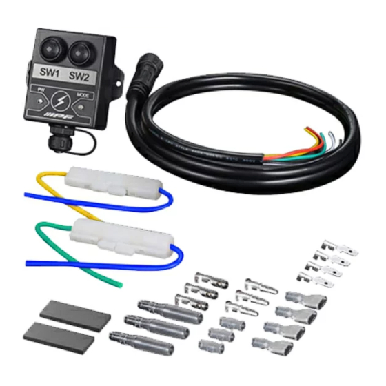
Component parts
№
①
WR Wireless Switch main unit
②
Harness
③
Fuse assembly
④
Terminal connector kit (3 x paired connector terminal and 4 x male flat terminal)
⑤
Double-sided tape
Wiring method
Before the installation work,
you must remove
the (-) terminal of the battery.
If the vehicle mounts 2 batteries,
remove both (-) terminals.
−
+
Do not pull strongly
the harness and connectors.
Name of product
Install the relay and harness
in a position where
it will not make contact
with high temperature surface.
(Such as engine, radiators,
or supercharger, exhaust pipes.)
Install the harness and cords
in a position where
it will not be scratched,
bent or pressed such
as in moving parts
(Pedals / Wires / Doors / Belts /
Pulleys).
In some cases, it may cause
the vehicle to catch fire.
WR-3
PN :
Qty.
1
1
2
1
2
All the connectors and terminals
should be solidly connected.
Harness and cords
should be securely tied
by cable ties or tapes.
Advertisement

Summary of Contents for ipf WR-3
- Page 1 This product is an optional accessory for harnesses with a relay specifically designed for IPF off-road lamps. Operation is not warranted if connected to an IPF harness without a relay or to products of other manufacturers, as this may cause failures to the product.
- Page 2 If radio interference occurs between this product and any other device, change location or stop using it. 1. Connect wires to harness of the lamp on/off switch Wiring methods vary depending on conditions of IPF off-road lamp set up. Refer to the following and make required wiring connections. Caution Please note that the flat terminals may be loose fit due to differences in thickness between terminals.
- Page 3 Wiring method example 3 : When the lamp on/off switch terminals are flat and two switches (lamps) are used. F i g . 1 Connect wires to one of the on/off switches shown in F i g . 3 Connect the other on/off switch as shown in F i g . 3 For the connections shown in , connect only the blue wire of the lamp on/off switch to the wire of the WR Switch using a flat terminal and a connector terminal.
- Page 4 F i g . 2 ON/OFF switch Insulate or waterproof Yellow or Green (unused) when not connected. Flat male terminals Removed terminal Connect Flat female terminals removed from ON/OFF switch Black Black Connect Yellow Yellow Terminal Fuse Green connectors Blue Green Blue Connect...
-
Page 5: Specifications
2. Mount the WR Switch main unit After wiring is completed, mount the main unit in a suitable place away from water and high temperatures, using supplied double-sided tape or separately prepared cable ties and screws. Avoid attaching double-sided tape to the nameplate label on the back side of the unit. Because the nameplate label is recessed from the surrounding area, which may cause the double-sided tape to become slightly uneven, resulting in the tape not being as strong as it should be. - Page 6 "Searching", if the app finds a WR switch in detection mode (If there is no WR Switch in detection mode in the vicinity, "WR-3 not found" will bedisplayed). When connecting, the distance between the WR Switch and your smartphone should be within 3m when there is nothing to block it.
-
Page 7: Useful Tips
【Basic operation】 Tap any switch button once and it will change from gray to red. This action gives +12V output for relay control to the harness control output of the WR Switch. Red indication on Switch button is light ON condition, and gray indicates light OFF condition. Tap again and the switch changes from red to gray, turning off +12V output. - Page 8 This will activate the detection mode. MODE LED light will start flashing and a new link will be ready. To search again, tap the "Research" button under "WR-3 not found" display with your smartphone close to the WR Switch main unit.
- Page 9 Press "Confirm" and your new name will be reflected on your app's display. Main unit name can also be changed from the default name WR-3 in the same way as for switches. Name change of the main unit will not be reflected until you restart it.
Need help?
Do you have a question about the WR-3 and is the answer not in the manual?
Questions and answers