Table of Contents
Advertisement
Quick Links
Advertisement
Table of Contents

Summary of Contents for asis P900
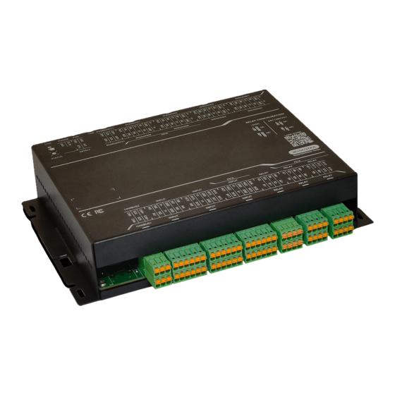
- Page 1 P900 Controller User Manual Revision1.3 / Jul 2015...
-
Page 3: Foreword
Information in this manual is subjected to change without further notice. ASIS Technologies make all efforts to ensure this Manual is up to date and corresponds to the product being shipped. However, ASIS Technologies assumes no responsibility for any errors that may occur in this manual. -
Page 4: Limited Warranty
Consumables items, such as batteries, have no warranty. ASIS Technologies does not assume any responsibility for damage or injury to person or property due to improper care, storage handling, abuse, misuse, normal wear and tear, or an act of God. -
Page 5: Table Of Contents
Table of Contents Foreword Limited Warranty Table of Contents 1.1 P900 Professional Series Web Based Controller Overview Controllers Features I/O onboard Wiegand port on boards Max Reader Support Modular subunits 1.2 Key Features of P900 family Professional Controller 1.3 Note to Installation 1.4a Dual Redundant Controller setup connectivity Diagram... - Page 6 5.5 Other Door Settings 5.6 Lift Controller Operation 5.7 Modular Fire Alarm 6.1 Input Configuration 6.2 Input Type 6.3 Supervised Input 6.4 End of Line Resistor 6.5 Non-Supervised Input 6.6 P90x Input Setting 6.7 Input Arm Setting 7.1 Output Connection 7.2 Output Select for Relay 7.3 Output Mode 8.1 P90x/ P91x /P9x0 Addressing...
- Page 7 Introduction...
-
Page 8: P900 Professional Series Web Based Controller Overview
P900 Professional Series Web Based Controller Overview P900 is a family name for a range of Professional Series, Card Access and Intrusion monitoring Controllers. Different configurations of controllers are available, and different modular addon subunits are in the families. Controllers Features I/O onboard... -
Page 9: Key Features Of P900 Family Professional Controller
Key Features of P900 family Professional Controller ● From dual redundant controller to expandable to 32-doors ● Navikey for setup and diagnostic at controller panel and quick credential enrolment ● Input Output only expandable module ● Reader Interface (ADNET,OSDP & Wiegand) ●... - Page 10 P901 has no readers, input or output terminal points. It is a barebones controller with CAN BUS, and LAN Port connection. P901 can link up with a second P901 thru Ethernet to form dual redundant controller systems. Modular subunit (P914,P918,P920,P930,P940) link up thru CAN bus to form a complete network.
- Page 11 P904 supports 8 readers in RS485, 16 inputs, 4 outputs terminal points. It comes with CAN BUS, and LAN Port connection. Modular subunit (P914,P918,P920,P930) link up thru CAN bus to form a complete network. Navikey mounted on the controller displays vital functional information of the controller. It doubles up as enrollment readers when necessary.
- Page 12 P908 supports 16 readers in RS485, 24 inputs, 12 outputs terminal points. It comes with CAN BUS, and LAN Port connection. Modular subunit (P914,P918,P920,P930) link up thru CAN bus to form a complete network. Navikey mounted on the controller displays vital functional information of the controller. It doubles up as enrollment readers when necessary.
- Page 13 Submodule P914 supports 8 readers, 16 inputs, 4 outputs terminal points. It comes with CAN BUS to communicate with the controller, A total of 3x P914 can be added to the controller. Submodule P918 supports 16 readers, 16 inputs, 4 outputs terminal points. It comes with CAN BUS to communicate with the controller, A total of 3x P918 can be add to the controller.
- Page 14 Submodule P920 has 0 readers, 32 inputs, 8 outputs terminal points. It comes with CAN BUS to communicate with the controller, A total of 4x P920 can be add to the controller. Page | 14...
- Page 15 Submodule P930 has 0 readers, 8 inputs, 32 outputs terminal points. It comes with CAN BUS to communicate with the controller, A total of 4x P920 can be add to the controller. Page | 15...
- Page 16 Page | 16...
-
Page 17: Note To Installation
Note to Installation The Installation and Mounting should observe the following: ● The controller should be kept at least 6 feet from any other RF emitting device. ● The controller should be mounted away possible of water leaking location or if in exterior location sealed to prevent water from seeping into the electronics. -
Page 18: Dual Redundant Controller Setup Connectivity Diagram
1.4a Dual Redundant Controller setup connectivity Diagram 1.4b Single Controller with addon board (Type A) 1.4c Single Controller with addon board (Type B) Page | 18... -
Page 19: Network Connectivity Diagram For P901
1.5 Network Connectivity Diagram for P901 *mixture of max 4 units of P920/P930 is supported P901 dual redundancy single line connectivity, P901 does not have any I/O or reader ports. Its primary function is to provide Controller dual redundancy. It serves CAN bus connected Modules for Access and Intrusion purposes. -
Page 20: Network Connectivity Diagram For P908 And Modules
1.6 Network Connectivity Diagram for P908 and Modules *mixture of max 4 units of P920/P930 is supported Figure 1.4 Single Line Drawing Connectivity for P908,P918,P920,P930 Page | 20... -
Page 21: Power And Data Connectivity For P908
Power and Data Connectivity for P908 Using DC power supply 13.8VDC 10 Amp, terminate the Connector input label as Power. Communicate to P908 via Ethernet port on LAN1 port. Communication RS485 device port to Readers Page | 21... -
Page 22: Product Specification
Product Specification Specification P901 P904 P908 Ethernet Host Link 1000Base T x 2 CAN Bus CAN Bus 1 and CAN Bus 2 InstaSTART Wizard DC Power Input 13.8VDC RS485 (Device Port) Up to 8x Readers Up to 16x Readers Wiegand Interface Alarm Input/Relay 16/4 24/12... - Page 23 Specification P914 P918 Ethernet Host Link CAN Bus CAN Bus 1 and CAN Bus 2 InstaStart Wizard DC Power Input 13.8VDC RS485 (Device Port) Up to 8x Readers Up to 16x Readers Wiegand Interface Alarm Input/Relay Output 16/4 24/12 Cardholders Event Buffers User Access Groups Holidays...
- Page 24 Weight 0.8Kg Specification P920 P930 P940 Ethernet Host Link CAN Bus CAN Bus 1 and CAN Bus 1 and CAN Bus 1 and CAN Bus 2 CAN Bus 2 CAN Bus 2 InstaStart Wizard DC Power Input 13.8VDC 13.8VDC 13.8VDC RS485 (Device Port) Wiegand Interface Alarm Input/Relay Output...
- Page 25 Product Mounting and Dimension Page | 25...
-
Page 26: All In One Enclosure
2.2 All in one Enclosure A total solution to house PSU, Battery and P900 modules the all in one Enclosure is available. Made of powder coated aluminum, the enclosure measures at 350x400x120mm. It is secure with key lock and built in with a tamper switch. Caters to site conditions where centralize cabling is a requirement. - Page 27 Figure 2.3 Interior layout Figure 2.4 All in one Enclosure with dimension Page | 27...
-
Page 28: All In One Enclosure Dimension
2.3 All in one Enclosure Dimension Figure 2.5 Front view dimensions Page | 28... - Page 29 Figure 2.6 Back view Mounting dimension Page | 29...
- Page 30 Power Supply Page | 30...
-
Page 31: Powering P908
Powering P908 P908 is powered by a 13.8V 10AMP PSU with Battery Charger. The PSU supplies power to the on board electronics, connected devices, and Electro Magnetic Lock. Total current draw from the PSU is recommended to not exceed 9Amp for system efficiency. Battery Backup Battery backup option is available with PSU built in charger. -
Page 32: Power Up P908 And Status Indicators
Power up P908 and Status Indicators When P908 is powered up, the Status LED on the right panel will turn on amber for 3 seconds and blinking green during operation. This indicates that the P908 is in normal operation. Figure 3.3 P908 Status LED Page | 32... - Page 33 Controller Module CAN Bus Connections Page | 33...
- Page 34 *P901, P904, P908 are master Controller. By itself they are controllers with web server, input, output, Reader port. *P901 is an exception as it does not have any input, output or reader port. To expand the numbers of input, outputs and readers port, P914, P918 can be added to P90x controller. In certain cases, the requirement calls for expansion of I/O only then P920, P930 is suitable.
- Page 35 Reader Connection Page | 35...
-
Page 36: P908 Wiegand Interface
For the Wiegand Interface, 4 standard card bit formats are supported. Wiegand 26bit, 35bit, 37bit and 32bit. The 32bit supports the ASIS Mifare 4 byte (32bit) Type A Card. A custom card bit format is available to define by the user and must be defined in IBSS software. - Page 37 The figure below shows the Wiegand Reader connection for P90x and P91x. The color code for various wires may differ with Reader vendors. Refer to manufacturer documentation for more information. Figure 4.1 P90x and P91x Reader Wiegand Connection Point Wire Color Legend Description Buzzer Green LED...
-
Page 38: P908 Rs-485 Reader Interface
P908 RS-485 Reader Interface With ASIS AMR17x series readers, the wiring terminates at (Port Device) on P2. It is recommended to use 1 pair twisted screen cable for the RS485 network and 1 pair 1.5mm cable for DC12V supply. Note: The RS-485 connection is polarized; user has to ensure correct polarity during installation. - Page 39 It is advisable to ground the screen cable to eliminate possible noise interferences. For the same communication loop, all screen cable should tie in to make a continuous link. Do not leave the screen wire un-terminated as it may short accidentally to on-board components.
- Page 40 Controller Operation Page | 40...
-
Page 41: Cluster Anti-Passback (Apb)
Each valid Cardholder must use his card to enter the door and exit the facility. There will be entry and exit records in the event report. For P900 anti-passback mode operates when an aux reader is attached via RS485 or Wiegand. -
Page 42: Arm Mode Setting
Mode Function Disable the APB Mode Disable Allow Entry/Exit with event reporting when there is APB violation Soft Disallowed Entry/Exit with event reporting when there is APB Hard violation Time Time Disallowed Entry/Exit with event report when APB violation reset Table 5.1 Anti-Passback Modes Arm Mode Setting P90x has 4 Arm Modes setting. - Page 43 Arm Mode: This mode is for normal operation. The door will be locked and monitored until a valid card is presented and P90x unlock the door with a time defined by Unlock Time setting in the Reader Configuration. Lock Mode: This will permanently lock the door.
-
Page 44: High Security Door Setting
High Security Door Setting Multi Card Access For highly secured areas, it may require the presence of more than one staff to unlock the door. P90x allows multiple cards to grant access. This mode may be set from the IBSS software. P90x allows multi-card access with up to 4-cards, and a number of authorized cards must be present before access is granted. -
Page 45: Other Door Settings
Door interlock Table 5.4 Other door settings Unlock Time: This is the time that P900 will unlock the door upon a valid card presentation. It can be set from 0 to 255 seconds. Pre-Alarm Time: C302 connected reader will sound the buzzer with a warning tone when the door is held open beyond this time. -
Page 46: Lift Controller Operation
5.6 Lift Controller Operation P900 support lifts access operation, upgrading from previous generation controller now each P900 network controller support max eight lift per controller (previous was four). One network can support maximum 176 relays output so if using 8 lifts evenly distributed each lift can support maximum 44 lift access level. -
Page 47: Modular Fire Alarm
5.7 Modular Fire Alarm P904,P908,P914,P918 boards are controllers and module boards that control door access. Each of these boards has dedicated fire alarm input. Installers can separately run fire alarm zone cable to different locations where the module is located. When a fire alarm occurs for a particular zone only the connect module board reader zone will react to the fire alarm. - Page 48 Input Page | 48...
-
Page 49: Input Configuration
Input Configuration This section provides information on input functions and wiring connection. There is 200ms noise filtering for all inputs. When input is activated within 200ms and then restored back to normal, the activation of this input will be ignored. Input Type All Inputs are designed to detect 4-state events in the “Supervised Mode”. -
Page 50: End Of Line Resistor
Normal State: This state indicates a NC external device is in normal condition. Activate State: This state indicated the NC external device is triggered i.e. become open circuit. Open Circuit: This indicates the line connection to the external device has been broken/open circuit. Short Circuit: This indicates that the line connection is short circuit. - Page 51 Figure 6.1 Typical connections for Exit Button 1 and Door Sensor Note: Use Normally Closed (NC) type input devices, such as Exit Button, Door Contact, etc., because Normally Open (NO) devices are not suitable. If the device is faulty on an open circuit, no detection is possible.
-
Page 52: Non-Supervised Input
Non-Supervised Input If the requirement is to detect ON/ OFF signal and line fault monitoring is not required, non-supervised mode may be used. To enable this mode, set DIP SW 1 and Switch 6 (LSS) should be turned “OFF”. No end of line resistor is required. Non-supervised input setting can detect 2 states: State Function... -
Page 53: Input Arm Setting
Fire Alarm Input Fire Alarm Fire Termination Monitoring Table 6.3 Default Input Settings for P90x Input Arm Setting All Input of P90x can be wired to monitoring devices with Dry contact normally close input for triggering monitoring. Mode Function Normal operation Disable arm operation Disarm Disarm during the time period defined by the Disarm... - Page 54 If the time zone is set to “09:00 – 16:59”, the table below illustrates the operation. Table 6.5 Disarm by Schedule Operation for Input Prior to 09:00, the input is in “Arm” mode, this means any activation of the input will trigger an alarm event.
- Page 55 Output Page | 55...
-
Page 56: Output Connection
Output Connection This section provides information on the Output connection to external devices. The Outputs has software configurable settings. The following figure shows the P90x output connection to EM Lock. Figure 7.1 P90x Output Connection Output Header Default Function Defaults Door Lock Output 1 (+ve) Reader 1 OP1 +... -
Page 57: Output Select For Relay
Output Select for Relay Relay can be set to different output configurations via jumper settings: ● NO (Normally Open) ● NC (Normally Close) ● 12V output in NO configuration ● 12V output in NC configuration The 4-pin header is for 12VDC or dry-contact (voltage free) output setting. The 3-pin header is for normally closed (NC)/ normally open (NO) output setting. -
Page 58: Output Mode
Output Mode An output may be set in any of the 5 Output modes. User must set the output mode to suit the application . Output Mode Function Output in activate mode Latch Output set to toggle mode Toggle Output is in pulse mode Pulse Output cycles with ON and OFF Cycle... - Page 59 Remain Activate Table 7.5 Latch Mode Example Figure 7.4 Latch Mode Operation Toggle mode: The output toggles between “On” and “OFF” states upon each input activation (or triggering). When Input 3 returns to normal state after each trigger, Output 1 remains at the state until the next activation.
- Page 60 Table 7.6 Toggle Mode Example Page | 60...
- Page 61 Figure 7.5 Toggle Mode Operation Pulse mode: Upon Input 3 activate, the Output 1 turns “ON” for a preset period (1 to 255 sec) and then “OFF” again. Input 3 Output 1 Normal Turn “ON” for 10 sec, then turn “OFF” Activate Turn “ON”...
- Page 62 Figure 7.6 Pulse Mode Timing Operation Note: An input activation before the pulse period expires extends the pulse period for the next 10 seconds. Cycle Mode: The Output cycles continuously with an “On Time” and “Off Time” (between 1 – 255 seconds).
- Page 63 Act by Schedule: This is timer control function by a weekly Schedule. The Output is activated by the Time Zones set in the Schedule. When there is activation prior to the start time, Output turns ON and will be turned OFF at the end time of the Time Zone. Figure 7.8 Act by Schedule Timing Control Operation Page | 63...
- Page 64 Addressing Page | 64...
-
Page 65: P90X/ P91X /P9X0 Addressing
P90x/ P91x /P9x0 Addressing P90x are IP based controllers, all addressing are IP addresses. Module unit connects to the controller via CAN bus. Each module is designated an address. Up to 3 P91x and 4 P9x0 can be connected to a P90x. Model P90x P91x... - Page 66 Page | 66...
Need help?
Do you have a question about the P900 and is the answer not in the manual?
Questions and answers