Table of Contents
Advertisement
Quick Links
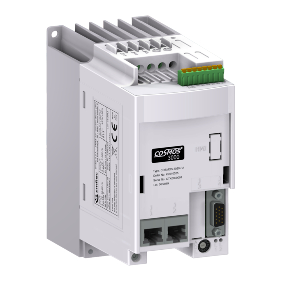
INVERTER COSMOS 3020
Smitec S.p.A., viale Vittorio Veneto 4, 24016 San Pellegrino Terme (BG), Italy, www.smitec.it
Installation, use and maintenance manual
BEFORE PUTTING THE COSMOS 3020 INVERTERS INTO SERVICE, CAREFULLY
READ THIS MANUAL AND FOLLOW ALL INSTRUCTIONS, IN ORDER TO ENSURE
MAXIMUM SAFETY
INVERTER COSMOS 3020
The technical data and drawings shown in this manual may have undergone subsequent
modifications; always refer to the latest version available.
Ver. 1.07
Installation, use and maintenance manual - EN
1
Advertisement
Table of Contents

Related Manuals for Smitec COSMOS 3020

Summary of Contents for Smitec COSMOS 3020
- Page 1 INVERTER COSMOS 3020 Installation, use and maintenance manual - EN Smitec S.p.A., viale Vittorio Veneto 4, 24016 San Pellegrino Terme (BG), Italy, www.smitec.it Installation, use and maintenance manual BEFORE PUTTING THE COSMOS 3020 INVERTERS INTO SERVICE, CAREFULLY READ THIS MANUAL AND FOLLOW ALL INSTRUCTIONS, IN ORDER TO ENSURE...
-
Page 2: Table Of Contents
INVERTER COSMOS 3020 Installation, use and maintenance manual - EN Summary 1 Preface ............................... 3 2 General warnings ............................4 3 Safety instructions ............................ 6 3.1 General information ..........................6 3.2 Precautions during handling and assembly ..................6 3.3 Precautions against risk of Electric Shock ..................7 3.4 Precautions against hot components .................... -
Page 3: Preface
INVERTER COSMOS 3020 Installation, use and maintenance manual - EN 1 Preface This manual provides all necessary information for the installation, use and maintenance of COSMOS 3020 inverters. The instructions included in this manual are addressed to the following professionals:... -
Page 4: General Warnings
MANUAL. THE EQUIPMENT MUST BE USED FOR PURPOSES DIFFERENT THAN THE ONES DESCRIBED IN THIS MANUAL; SMITEC S.p.A. SHALL NOT BE HELD RESPONSIBLE FOR ANY DAMAGES, INCON- VENIENCES OR ACCIDENTS DUE TO THE NON-COMPLIANCE WITH THESE PRESCRIPTIONS. In order to make the manual consultation easier, the following symbols have been adopted: Indication of “PROHIBITED ACTION”. - Page 5 INVERTER COSMOS 3020 Installation, use and maintenance manual - EN The symbol “USE OF INDIVIDUAL PROTECTIONS” means that protective gloves must be worn. The symbol “USE OF INDIVIDUAL PROTECTIONS” means that protective glasses must be worn. Indication of “INFORMATION OF PARTICULAR RELEVANCE”.
-
Page 6: Safety Instructions
Make sure that the personnel is qualified and adequately informed about the risks he may run and how to avoid them. The COSMOS 3020 inverters is authorized can be used only after the classification of the machine operating area and after checking the safety levels, which must correspond to the assembly safety levels. -
Page 7: Precautions Against Risk Of Electric Shock
INVERTER COSMOS 3020 Installation, use and maintenance manual - EN 3.3 Precautions against risk of Electric Shock The high voltage of some accessories and components in the inverter might cause electro- cution, if the user came into contact with them. Be careful to the terminal boards and to the motor/dynamic brake connection. -
Page 8: Precautions Against Hot Components
INVERTER COSMOS 3020 Installation, use and maintenance manual - EN 3.4 Precautions against hot components WARNING The parts of the apparatus can reach an extremely high temperature in operating mode or post-operation; take particular care not to touch the parts of the equipment in these cases, or use special protections and precautions during handling: HOT SURFACE, RISK OF BURN. -
Page 9: Data Sheet
4 Data sheet 4.1 Description The COSMOS 3020 inverters are designed for the simultaneous control of two three-phase asynchronous mo- tors; the electronic boards are housed inside a sturdy plastic case, and the dissipation of power is ensured by an aluminium heatsink. To ensure high reliability and quiet operation, they do not have a cooling fan (“fanless”). -
Page 10: Reference Documents
Installation, use and maintenance manual - EN 4.2 Reference documents Code Description DK400211 COSMOS 3020 user and programming manual 4.3 Technical data 4.3.1 Environmental characteristics 0° ÷ 40°C without derating (full output current) Operating temperature 0° ÷ 55°C with derating (reduced output current) 40°C without derating (full output current) -
Page 11: Power Supplies
INVERTER COSMOS 3020 Installation, use and maintenance manual - EN Air humidity during storage 5 ÷ 95% Air humidity during transport 5 ÷ 95% 1000 m (on the sea level) at nominal output current Maximum altitude 2000 m (on the sea level) with current derating... -
Page 12: Digital Inputs
INVERTER COSMOS 3020 Installation, use and maintenance manual - EN Size maximum asynchronous motor 0.37kW / 1/2 HP (power to the crankshaft) Active power deliverable 1 kW max. Peak output current 12 A Phase-to-phase short circuit, overload, inverter over tem-... -
Page 13: Configurations / Order Codes
INVERTER COSMOS 3020 Installation, use and maintenance manual - EN 4.4 Configurations / order codes Up to date, we defined some standard configurations of inverters, with their order code and type number (4 figures, indicating the series, the maximum current and the release). These data are indicated on the inverter label. -
Page 14: Model Code
Installation, use and maintenance manual - EN 4.5 Model code The specific features of a COSMOS 3020 inverter are defined by an alpha-numeric code printed on the device label, near the MODEL code. Here is the code table: MO DEL * * * * * . -
Page 15: Accessories
Installation, use and maintenance manual - EN 4.6 Accessories The COSMOS 3020 inverters are supplied with the complete set of detachable connectors for power and I / O connections (where provided). The same connectors can be ordered separately as well as other accessories not included in the inverter. -
Page 16: Mechanical Specifications
INVERTER COSMOS 3020 Installation, use and maintenance manual - EN 4.8 Mechanical specifications 4.8.1 Weight The following table shows the weight: Type Weight (kg) KZ010525 1.0 kg 4.8.2 Model size Ver. 1.07... -
Page 17: Installation And Start-Up
• Make sure the installation manual is present. Positioning and installation The inverters COSMOS 3020 are designed for operating in closed electrical operating ar- eas (as defined in the EN 61800-5-1 standard); installation outside an electrical panel is not allowed. - Page 18 Installation, use and maintenance manual - EN The inverters COSMOS 3020 generate a certain quantity of heat during operation; the electrical panel must be able to dissipate it, in order to avoid an excessive temperature increase. A common solution consists in install- ing cooling fans or a conditioner.
-
Page 19: Electrical Connections
INVERTER COSMOS 3020 Installation, use and maintenance manual - EN Electrical connections The device described in this manual is equipped with screw terminal blocks for high voltage electrical connec- tions (mains power supply, motor outputs, PE (Ground) protective conductor), while the extra low voltage con- nections (24V power supply, 24V digital inputs) are made via detachable connectors. -
Page 20: Mains Power
INVERTER COSMOS 3020 Installation, use and maintenance manual - EN 5.3.1 Mains power These are the connections of 230VAC supply. WARNING Risk of Electric Shock; wait at least No. 360 seconds (6 minutes) after disconnecting power. AVERTISSEMENT Risque de choc électrique; attendez au moins 360 secondes (6 minutes) après la mise hors tension. -
Page 21: Cables And Protective Devices
INVERTER COSMOS 3020 Installation, use and maintenance manual - EN WARNING For safety reasons, the device must always operate with PE (Ground) connected; risk of electric shock! PE (Ground) connection must be made by means of the specific terminal and not merely with screws. - Page 22 INVERTER COSMOS 3020 Installation, use and maintenance manual - EN The terminal board contacts must be tightened by means of a flat-blade screwdriver (blade width: 3.5 mm); the recommended tightening torque is equal to 0.55 Nm ±10%. In order to protect the device and the power cables, install a protective device against overload and short-cir- cuit.
- Page 23 INVERTER COSMOS 3020 Installation, use and maintenance manual - EN Protection for use exclusively in compliance with EN 61800-5-1 If the inverter protection is ensured by fuses, their size must guarantee the protection of both the device and the conductors. If you use 10x38mm class gG cartridge-type fuses, their minimum size for ensuring the inverter full-power operation is 12 A.
-
Page 24: Installation Criteria For Ul Certification
INVERTER COSMOS 3020 Installation, use and maintenance manual - EN Protection for UL applications according to UL 61800-5-1 and CSA C22.2 No.274 The characteristics of the recommended fuses are summarized in the following tables: COSMOS 3020 Marking Mersen Model FR10GR69V16... -
Page 25: Motor
INVERTER COSMOS 3020 Installation, use and maintenance manual - EN 5.3.2 Motor The power wiring must be made by means of a 6-pole terminal board; the following picture shows the pin con- figuration. Motor wiring Label Signal Phase output W - motor 1... - Page 26 INVERTER COSMOS 3020 Installation, use and maintenance manual - EN Due to the high noise levels generated by PWM modulation on the motor outputs, it is obligatory to use a shield- ed cable for connecting motors. The shield must be connected to earth on both sides with a low-impedance connection (such as a metal cam);...
-
Page 27: Auxiliary Power Supply And 24V Digital Inputs
INVERTER COSMOS 3020 Installation, use and maintenance manual - EN 5.3.3 Auxiliary power supply and 24V digital inputs The inverter is equipped with a connector for connecting the 24V auxiliary power supply and the digital inputs. The pinout of the connector provided for this purpose is shown in the following paragraphs. -
Page 28: Auxiliary Power Supply
INVERTER COSMOS 3020 Installation, use and maintenance manual - EN 5.3.3.1 24V auxiliary power supply A 24VDC auxiliary voltage is required for operation of the control logic and other peripherals such as the en- coder. In the absence of this power supply, the inverter will not work even if the 230VAC main power supply is present. -
Page 29: Digital Inputs
INVERTER COSMOS 3020 Installation, use and maintenance manual - EN 5.3.3.2 24V digital inputs The inverter is equipped with 4 general purpose 24V digital inputs. These inputs are typically used to acquire data from sensors with digital output, which are very common in industry (such as photocells, limit switches, etc.). -
Page 30: Incremental Encoder
An encoder is used as a feedback device for reading and controlling the motor position and speed. Inverters COSMOS 3020 are equipped with a peripheral device that can acquire data from incremental digital encoders, which are powered by 5 VDC and have differential output signals. Differential outputs offer grater noise rejec- tion than common single-ended outputs. - Page 31 INVERTER COSMOS 3020 Installation, use and maintenance manual - EN The following picture shows an example of connection; in case of asynchronous motor, the Hall sensors are not included. The wiring must be made by a shielded cable; the shield on the cable end on the inverter side must be soldered directly to the connector shell.
-
Page 32: Field Bus Flxio
INVERTER COSMOS 3020 Installation, use and maintenance manual - EN 5.3.5 Field bus FlxIO Refer to the FlxIO bus integration and FlxMod system DK400076 manual for the correct definition of the connection topology of the FlxIO bus. The inverter is equipped with an interface for FlxIO field bus. This bus, based on a RS485 electrical non-insu- lated interface, performs a reliable, real-time control of complex applications. -
Page 33: Manual Addressing
INVERTER COSMOS 3020 Installation, use and maintenance manual - EN 5.3.5.1 Manual addressing Each slave in a FlxIO bus must have its address, which can be modified in a very easy way. To this purpose, the inverter is equipped with a rotary switch (on the front panel), with 16 different positions (from 0 to F, in hex- adecimal notation). -
Page 34: Automatic Addressing
INVERTER COSMOS 3020 Installation, use and maintenance manual - EN Since the address is read only when the device is switched on, the address must be set before powering the system, otherwise it will not be possible to see the modifications until the system re-starts. -
Page 35: Diagnostics
INVERTER COSMOS 3020 Installation, use and maintenance manual - EN 6 Diagnostics 6.1 Signalling LEDs On the front panel of the device there are two LED indicators identified with the letters L1 and L2. They indicate the status of the FlxIO field bus of the device. - Page 36 INVERTER COSMOS 3020 Installation, use and maintenance manual - EN They have the following meaning according to the FlxIO standard, based on their switching on and off and the frequency with which they flash: L1 (red) L2 (green) Function Flash 1Hz...
-
Page 37: Firmware Update
Installation, use and maintenance manual - EN 7 Firmware update Following improvements or functionality additions, the inverters COSMOS 3020 can be upgraded with a newer firmware version. This operation can be implemented directly via the FlxIO field bus (teleprogramming); if the master device de- tects that the inverter is programmed with a FW version different from the one loaded in memory, it automati- cally reprograms it. -
Page 38: Storage
INVERTER COSMOS 3020 Installation, use and maintenance manual - EN 8 Storage The equipment can be stored in its original package for the necessary period; it must be kept in a covered area even if it is packed. Protect the equipment from dust and weather. -
Page 39: Maintenance
Installation, use and maintenance manual - EN 9 Maintenance SMITEC S.p.A. does not require any ordinary maintenance to be performed on inverters COSMOS 3020; re- member that no component may be removed from the device, since such removal may compromise the safety level. -
Page 40: Disposal And Demolition
INVERTER COSMOS 3020 Installation, use and maintenance manual - EN 10 Disposal and demolition The equipment must be disposed of in compliance with the legislation in force in the country where it is in- stalled. In case of partial disposal of the equipment (frame, dissipater, electronic boards), the different materials must be separated (aluminium, plastic, etc.). -
Page 41: Analytical Index
INVERTER COSMOS 3020 Installation, use and maintenance manual - EN 11 Analytical index Active power ............ 12 Short-circuit current ......... 11 Air humidity ............10 Start-up ............17 Asynchronous motor ........12 Storage temperature ........10 Automatic addressing ........34 Switching frequency ........
Need help?
Do you have a question about the COSMOS 3020 and is the answer not in the manual?
Questions and answers