Table of Contents
Advertisement
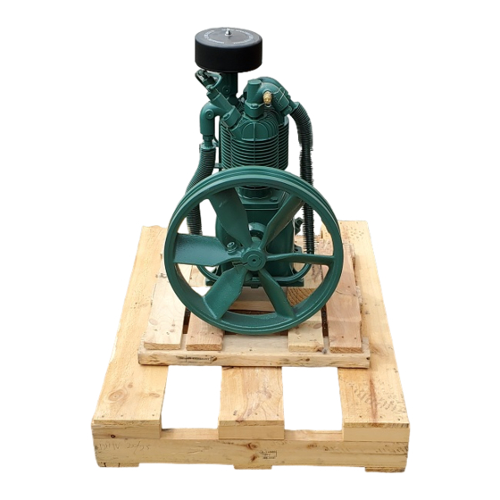
PL Series 2-Stage Pressure Lubricated Air
Compressor & Units Featuring the PL15A Pump
THIS MANUAL CONTAINS IMPORTANT SAFETY INFORMATION AND SHOULD ALWAYS BE
AVAILABLE TO THOSE PERSONNEL OPERATING THIS UNIT.
READ, UNDERSTAND AND RETAIN ALL INSTRUCTIONS BEFORE OPERATING THIS
EQUIPMENT TO PREVENT INJURY OR EQUIPMENT DAMAGE.
VPL5-6 UNIT
Form No. F92193PLA
VER: 01 04/23/02
WARNING
C354-A
(Ref. Drawing)
OPERATION/MAINTENANCE
MANUAL & PARTS LIST
PL15A PUMP
C326-A
(Ref. Drawing)
Advertisement
Table of Contents

Related Manuals for Compressed Air Advisors Champion PL Series

Summary of Contents for Compressed Air Advisors Champion PL Series
- Page 1 OPERATION/MAINTENANCE MANUAL & PARTS LIST PL Series 2-Stage Pressure Lubricated Air Compressor & Units Featuring the PL15A Pump WARNING THIS MANUAL CONTAINS IMPORTANT SAFETY INFORMATION AND SHOULD ALWAYS BE AVAILABLE TO THOSE PERSONNEL OPERATING THIS UNIT. READ, UNDERSTAND AND RETAIN ALL INSTRUCTIONS BEFORE OPERATING THIS EQUIPMENT TO PREVENT INJURY OR EQUIPMENT DAMAGE.
-
Page 2: Maintain Compressor Reliability
MAINTAIN COMPRESSOR RELIABILITY AND PERFORMANCE WITH ® GENUINE CHAMPION COMPRESSOR PARTS AND SUPPORT SERVICES ® Champion Compressor genuine parts, manufactured to design tolerances, are developed for optimum dependability – specifically for Champion compressor systems. Design and material innovations are the result of years of experience with hundreds of different compressor applications. -
Page 3: Table Of Contents
TABLE OF CONTENTS _______________________________________________________ Subject Page Maintain Compressor Reliability ........................2 Explanation Of Safety Instruction Symbols And Decals ................4 Safety And Operation Precautions........................ 5 Introduction ..............................6 Warranty................................ 6 Dimensions And Specifications........................7 Installation ...............................8 & 9 Operation............................10 & 11 Maintenance.......................... -
Page 4: Explanation Of Safety Instruction Symbols And Decals
EXPLANATION OF SAFETY INSTRUCTION SYMBOLS AND DECALS DANGER Indicates immediate hazards which will result in severe injury or death. WARNING Indicates hazards or unsafe practice which could result in severe injury or death. CAUTION Indicates hazards or unsafe practice which could result in damage to the Champion compressor or minor injury. -
Page 5: Safety And Operation Precautions
SAFETY AND OPERATION PRECAUTIONS ___________________________________________________________________________________ Because an air compressor is a piece of machinery with moving and rotating parts, the same precautions should be observed as with any piece of machinery of this type where carelessness in operation or maintenance is hazardous to personnel. In addition to the many obvious safety rules that should be followed with this type of machinery, the additional safety precautions as listed below must be observed: Read all instructions completely before operating air compressor or unit. -
Page 6: Introduction
INTRODUCTION ______________________________________________________________________ Champion PL Series compressors are the result of advanced engineering and skilled manufacturing. To be assured of receiving maximum service from this machine the owner must exercise care in its operation and maintenance. This book is written to give the operator and maintenance department essential information for day-to-day operation, maintenance and adjustment. -
Page 7: Dimensions And Specifications
TWO STAGE AIR COMPRESSORS - MODEL PL15A DIMENSIONS ITEM PL15A Base-Width Bolt Down-Width 4-3/8 Bolt Down to Edge Base to Crank Ctr 5-1/2 Overall Width 16-7/8 Overall Height 23-1/4 Bolt Down Hole Dia. 15/32 Base-Depth 7-1/2 Bolt Down Depth 5-3/4 Bolt Down to Edge Bolt Hole to Wheel (Max.) 3-3/16... -
Page 8: Installation
INSTALLATION WARNING Do not operate unit if damaged during shipping, handling or use. Operating unit if damaged may result in injury. Permanently installed compressors must be located in a clean, well ventilated dry room so compressor receives adequate supply of fresh, clean, cool and dry air. It is recommended that a compressor, used for painting, be located in a separate room from that area wherein body sanding and painting is done. - Page 9 INSTALLATION (CONT’D) All models require a properly sized magnetic starter as specified in the National Electric Code (NEC). See Figure 1-1 for simplex wiring diagram and Figure 1-2 for duplex wiring diagram If ordered with a factory mounted magnetic starter, compressor is wired at factory. It is necessary only to bring lines from a properly sized disconnect switch to the magnetic starter mounted on the unit.
-
Page 10: Operation
GROUNDING INSTRUCTIONS This product should be connected to a grounded, metallic, permanent wiring system, or an equipment- grounding terminal or lead on the product. AIR LINE PIPING Connection to air system should be of the same size, or larger, than discharge pipe out of unit. The table gives recommended minimum pipe sizes. - Page 11 OPERATION (CONT’D) Initial Start Up 1. Inspect unit for any visible signs of damage that would have occurred in shipment or during installation. 2. Pull main disconnect switch to unit to assure that no power is coming into the unit. “Lock Out” or “Tag Out”...
-
Page 12: Maintenance
GUIDE TO MAINTENANCE For Service contact an authorized Champion distributor. All requests should include model number and serial number. To obtain reliable and satisfactory service, this unit requires a consistent preventive maintenance schedule. Maintenance schedule form is included to aid in keeping the proper records. - Page 13 EVERY 90 DAYS OR 500 HOURS MAINTENANCE Change crankcase oil and oil filter. Use only Champlub recip lubricant. Check entire system for air leakage around fittings, connections, and gaskets, using soap solution and brush. Tighten nuts and cap screws as required. Check and clean compressor valves as required.
- Page 14 GENERAL MAINTENANCE (Cont'd.) HYDRAULIC UNLOADER: This compressor is equipped with an unloading device operated by oil pressure. When the compressor is turned off, the unloader will open resulting in a short burst of air from the unloader (released through the intake filter.). When the compressor is restarted, as soon as oil pressure reaches normal operation range (between 15 and 30 PSIG) the unloader valve closes and the compressor begins to pump air.
-
Page 15: Compressor Pilot Valve Differential Pressure Adjustment
COMPRESSOR PILOT VALVE PRESSURE ADJUSTMENT Proceed with the following instructions while compressor is running: Loosen locknut (2) and back off several turns. Check reading on the tank pressure gauge. Set the pressure to 30 psig differential (unload at 170 psig, reload at 140 psig). Turn nut (3) clockwise to increase differential pressure or counterclockwise to decrease differential pressure. -
Page 16: Compressor Oil Specifications
COMPRESSOR OIL SPECIFICATIONS Compressors are factory filled with Champlub hydrocarbon based recip lubricant. This is an ISO 100 non-detergent industrial lubricant with rust and oxidation inhibitors specially formulated for reciprocating compressors. It is recommended this compressor be maintained using this oil for ambient temperatures above 32°F. -
Page 17: Trouble Shooting Guide
TROUBLE SHOOTING CHART FOR COMPRESSOR WARNING Always disconnect unit from power supply and relieve all pressure from air tank before performing any maintenance. “Tag Out” or “Lock Out” all power sources. Failure to do so may result in equipment damage or injury. - Page 18 Troubleshooting Chart (cont’d) Symptom Possible Cause(s) Corrective Action Low or loss of oil pressure Low crancase level. Check oil level. Add oil if required. Oil pickup screen clogged. Drain oil from crankcase. Remove oil pickup screen and clean. Reinstall screen and all clean oil to crankcase.
- Page 19 UNIT REPAIR PARTS ILLUSTRATION MODELS: HPL3-6, HPL3-8, HPL3-12, HPL5-6, HPL5-8, HPL5-12, HPL7F-8 & HPL7-12 C-358-A (Ref. Drawing) REPAIR PARTS LIST MODEL HPL3-6 HPL3-8 HPL3-12 HPL5-6 HPL5-8 HPL5-12 HPL7F-8 HPL7F-12 Pump PL15A PL15A PL15A PL15A PL15A PL15A PL15A PL15A Pressure Gauge M519C M519C M519C...
- Page 20 UNIT REPAIR PARTS ILLUSTRATION MODELS: VPL3-6, VPL3-8, VPL3-12, VPL5-6, VPL5-8, VPL5-12, VPL7F-8, & VPL7F-12 C-357A (Ref. Drawing) REPAIR PARTS LIST MODEL VPL3-6 VPL3-8 VPL3-12 VPL5-6 VPL5-8 VPL5-12 VPL7F-8 VPL7F-12 Pump PL15A PL15A PL15A PL15A PL15A PL15A PL15A PL15A Pressure Gauge M519C M519C M519C...
- Page 21 UNIT REPAIR PARTS ILLUSTRATION MODELS: BPL-3, BPL-5, & BPL-7F C-355-A (Ref. Drawing) REPAIR PARTS LIST MODEL BPL-3 BPL-5 BPL-7F Pump PL15A PL15A PL15A Belt Guard Z307 Z307 Z307 Base Plate P09195C P09195C P09195C Motor 3 HP 5 HP 7.5 HP P07981A Pulley Pulley...
-
Page 22: Unit Repair Parts List
UNIT REPAIR PARTS ILLUSTRATION MODELS: HPL5D-8, HPL5D-12, & HPL7DF-25 C359-A REPAIR PARTS LIST (Ref. Drawing) MODEL HPL5D-8 HPL5D-12 HPL7DF-25 Pump PL15A PL15A PL15A Pressure Gauge M519C M519C M519C Belt Guard Z307 Z307 Z307 Belt Guard Z1432 Z1432 Z1432 Drain Valve M2684 M2684 M2684... - Page 23 C311-A (Ref. Drawing)
- Page 24 Repair Parts List Compressor Pump Model PL15A Ref. Part Description Qty. Number Crankcase P07383D 1/4" Pipe plug M2326 Oil level gauge RE714 3/8 x 4" Pipe nipple M492 3/8" Pipe cap M461 O-Ring P07428A Oil screen P07381B Spring P07427A 1/2" Pipe plug M998B Crankshaft P11544C...
- Page 25 Repair Parts List Compressor Pump Model PL15A Ref. Part Description Qty. Number Piston pin bearing R1037 Connecting rod bolt M1583 Low pressure piston with pin ZR154 Piston pin R1021 Piston pin retaing ring R10102 Low pressure piston ring set Z798 High pressure piston with pin ZP02709C High pressure piston ring set...
- Page 26 Repair Parts List Compressor Pump Model PL15A Ref. Part Description Qty. Number Valve gasket P09170A Unloader spring P01882A Guide stem P09296A Unloader finger P14119A Locking hex nut P09086A Unloader piston P09923A High pressure intake manifold P12304B Interstage pressure relief valve P03592A Valve gasket P04136A...
-
Page 27: Compressor Repair Parts List
COMPRESSOR REPAIR PARTS ILLUSTRATION Model: PL15A C312-A (Ref. Drawing) Repair Parts List Models PL15A Ref. No. Description Part Number Qty. Control valve tube P10835A Head unloader tube P10832A Shuttle valve tube P10836A Breather tube P10838A 3/8 x 1/4" NPT Straight compression fitting M2864 1/4 x 1/4 x 1/8"... -
Page 28: Unit Hazard Decal Listing
UNIT HAZARD DECAL LISTING PAGE DESCRIPTION PART NO. PRODUCT LIABILITY DECAL SHEET - MASTER P10157A Unit Pressure Setting NOT USED DANGER – Breathing Air DANGER – Drain Tank Daily WARNING – Pressure/Safety Valve NOT USED DANGER – Valve Maintenance DANGER – High Voltage WARNING –... -
Page 29: Unit Hazard Decals
UNIT HAZARD DECALS... -
Page 30: Pump Hazard Decals
PUMP HAZARD DECALS... -
Page 31: Record Of Maintenance Service
RECORD OF MAINTENANCE SERVICE DAILY ● CHECK OIL LEVEL ● DRAIN MOISTURE FROM TANK WEEKLY MONTHLY EVERY 3 MONTHS ● CLEAN FILTER ● INSPECT AIR SYSTEM ● CHANGE OIL & OIL FILTER ● CLEAN COMPRESSOR ● INSPECT VALVE ASSEMBLIES ● CHECK V-BELTS ●... - Page 32 FOR PARTS: REFER TO PARTS DEPOT LIST ACCOMPANYING THIS MANUAL. Champion 1301 North Euclid Avenue Princeton, Illinois 61356 USA Phone (815) 875-3321 Fax (815) 872-0421 Plants in Princeton, IL, and Manteca, CA Due to Champion’s continuing product development program, Copyright 8 2002 Gardner Denver, Inc. specifications and materials are subject to change without notice or Printed in U.S.A.
Need help?
Do you have a question about the Champion PL Series and is the answer not in the manual?
Questions and answers