Table of Contents
Advertisement
Available languages
Available languages
Quick Links
Advertisement
Table of Contents

Summary of Contents for Central Lobao ASPAD1000
- Page 1 ASPAD1000...
-
Page 2: Table Of Contents
1. INTRODUCTION ..........31 Índice 2. SAFETY ............32 1. INTRODUÇÃO ............ 3 3. PANEL DESCRIPTION ........33 2. SEGURANÇA ............4 4. SYMBOLS OF LCD DISPLAY ......35 3. DESCRIÇÃO DO PAINEL ........5 5. TECHNICAL SPECIFICATIONS ......36 4. -
Page 3: Introdução
1. INTRODUÇÃO Parabéns por ter adquirido a Pinça Amperimétrica Digital True RMS, modelo ASPAD1000 da ASLO. Desenvolvido para especialistas, este modelo da Aslo Eletric foi projetado para a medição de corrente e tensão AC/DC em True RMS. Visor retro iluminado para facilitar a leitura em ambientes pouco iluminados. -
Page 4: Segurança
2. SEGURANÇA Este símbolo indica que o operador deve consultar uma explicação nas instruções de operação para evitar ferimentos pessoais ou danos ao medidor. Terra Duplo de Isolamento PRECAUÇÕES • Antes de utilizar, o medidor deve ser aquecido por 30 segundos; •... -
Page 5: Descrição Do Painel
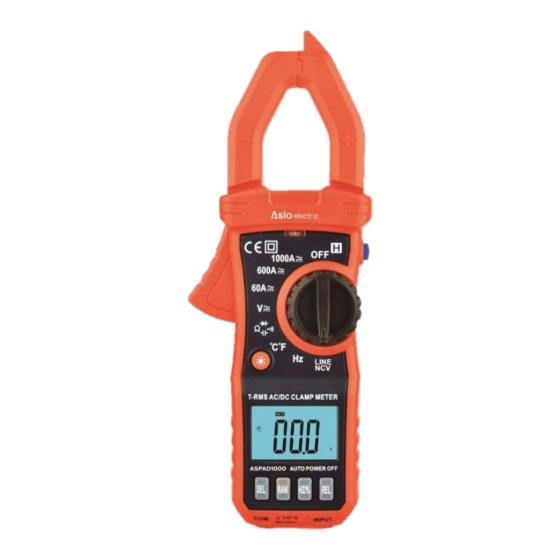
3. DESCRIÇÃO DO PAINEL 1. Sensor NCV 2. Garra 3. Lanterna 4. Indicador Led de NCV 5. Retenção de Dados 6. Alavanca de abertura da Garra 7. Comutador Rotativo 8. Botão de Iluminação do Visor / Lanterna 9. Visor LCD 10. - Page 6 No. Função Descrição Coloque o Comutador Rotativo na faixa NCV, O visor LCD exibirá EF. Aproxime a extremidade dianteira do medidor (onde se encontra o sensor) ao objeto ou ao Deteção NCV circuito a ser testado. Ao detetar tensão, o visor LCD exibirá “- - “. O medidor emitirá...
-
Page 7: Símbolos Do Visor Lcd
4. SÍMBOLOS DO VISOR LCD Símbolo Descrição Símbolo Descrição Retenção de Dados Indicação de Baixa Tensão Teste de Díodo Teste de Continuidade Retenção de Valor Máx. Função de Filtro Passa-Baixo Deteção de Tensão Sem Contacto Corrente de Pico Unidade de Tensão Unidade de Corrente Unidade de Frequência Unidade de Capacitância... -
Page 8: Especificações Técnicas
5. ESPECIFICAÇÕES TÉCNICAS • Temperatura de operação: 0 ~ 40 ℃ / Humidade: <80% RH • Temperatura de armazenamento: -10 ~ 60 ℃ / Humidade: <70% RH (remova a bateria) • Tensão máxima de entrada entre o terminal de entrada e o terra: 600VRMS •... - Page 9 5.3 Corrente DC Faixa Resolução Precisão 40A/60A 0.01A 400A/600A 0.1A ±(2.5% leitura + 10 dígitos 1000A 5.4 Tensão DC Faixa Resolução Precisão 200mV/400mV/600mV 0.1mV ±(0.5% leitura + 3 dígitos) 2V/4V/6V 0.001V 20V/40V/60V 0.01V ±(0.8% leitura + 5 dígitos) 200V/400V/600V 0.1V 600V/1000V ±(1.0% leitura + 5 dígitos) Impedância de entrada: 10MΩ;...
- Page 10 5.6 Resistência Faixa Resolução Precisão 200Ω/400Ω/600Ω 0.1Ω ±(1.0% leitura + 10 dígitos) 2KΩ/4kΩ/6kΩ 0.001kΩ 20kΩ/40kΩ/60kΩ 0.01kΩ ±(0.8% leitura + 5 dígitos) 200kΩ/400kΩ/600kΩ 0.1kΩ 2MΩ/4MΩ/6MΩ 0.001MΩ 20MΩ/40MΩ/60MΩ 0.01Ω ±(2.0% leitura + 10 dígitos) Proteção contra sobrecarga: 250VDC ou AC RMS 5.7 Díodo e Continuidade Faixa Função Exibe tensão direta aproximada do díodo, reverso mostra “OL”...
- Page 11 5.9 Frequência Faixa Resolução Precisão 10Hz 0.01Hz 100Hz 0.1Hz 1kHz 0.001kHz 10kHz 0.01kHz ±(0.5% leitura + 2 dígitos) 100kHz 0.1kHz 1MHz 0.001MHz 10MHz 0.01MHz Proteção contra sobrecarga: 250VDC ou AC RMS 5.10 Capacitância Faixa Resolução Precisão 10nF 0.01nF ±(4.0% leitura + 25 dígitos) 100nF 0.1nF 1µF...
-
Page 12: Instruções De Operação
6. INSTRUÇÕES DE OPERAÇÃO NOTA: Leia e compreenda todas as instruções de Aviso e Cuidado neste manual de operação antes de usar este medidor. Coloque o interruptor rotativo na posição OFF quando o medidor não estiver em uso. Medição de Corrente •... - Page 13 Medição de Resistência • Para evitar choque elétrico, desconecte a energia da unidade em teste e descarregue todos os condensadores antes de realizar qualquer medição de resistência. o Coloque o Comutador Rotativo na posição e pressione o botão SEL para selecionar a faixa .
- Page 14 Deteção de Tensão sem contacto (NCV) • Devido a fontes de interferência externas, esta função pode causar deteção incorreta de tensão, o resultado da deteção é apenas para referência. • Coloque o Comutador Rotativo na posição NCV, aproxime a extremidade dianteira do medidor (onde se encontra o sensor) ao objeto ou ao circuito a ser testado, o LED indicador piscará...
-
Page 15: Manutenção
7. MANUTENÇÃO Aviso: • Para evitar choque elétrico, desconecte os cabos de teste de qualquer fonte de tensão antes de remover a tampa traseira ou a tampa da bateria ou do fusível. • Para evitar choque elétrico, não opere o medidor até que a tampa da bateria e do fusível esteja no lugar e fixada com segurança. -
Page 16: Certificado De Garantia
Declaramos sob nossa exclusiva responsabilidade que estes artigos com a designação PINÇA AMPERIMÉTRICA DIGITAL T- RMS com o código ASPAD1000 estão de acordo com as disposições da Directiva 2014/35/EU, relativa à harmonização das legislações dos Estados-Membros respeitantes aos equipamentos elétricos projetados para uso dentro de certos limites de tensão, cumprindo as seguintes normas:... -
Page 17: Introducción
1. INTRODUCCIÓN Felicitaciones por su compra del medidor de pinza digital True RMS de ASLO ASPAD1000. Desarrollado para expertos, este modelo de Aslo Electric fue diseñado para medir corriente y voltaje de AC / DC en True RMS. Pantalla retroiluminada para facilitar la lectura en entornos poco iluminados. -
Page 18: Seguridad
2. SEGURIDAD Este símbolo indica que el operador debe consultar una explicación en las Instrucciones de funcionamiento para obtener más información. Tierra Doble Aislamiento PRECAUCIONES • Antes de operar la medición, el medidor debe calentarse durante 30 segundos • Inspeccione la condición de los cables de prueba y el medidor en busca de daños antes de operar el medidor. -
Page 19: Descripción Del Panel
3. DESCRIPCIÓN DEL PANEL 1. Detección de NCV 2. Pinza de Corriente 3. Linterna 4. Indicador Led de NCV 5. Retención de Datos 6. Palanca de Apertura de la Garra 7. Interruptor Giratorio 8. Botón de Retroiluminación/Linterna 9. Pantalla LCD 10. - Page 20 No. Función Descripción Ajuste el Rotary Switch en el rango NCV. La pantalla LCD mostrará EF. Acerque el extremo frontal del medidor (donde está el sensor) al objeto o Detección de NCV circuito a probar. Al detectar voltaje, la pantalla LCD mostrará "- -". El medidor emitirá...
-
Page 21: Símbolos De Pantalla Lcd
4. SÍMBOLOS DE PANTALLA LCD Symbol Descripción Symbol Descripción Retención de Datos Indicación de Baja Tensión Prueba de diodos Verificación de Continuidad Valor Máximo Retenido Función de Filtro de Paso Bajo Detección de Voltaje Sin Contacto Pico de Corriente Unidad de Voltaje Unidad de Corriente Unidad de Frecuencia Unidad de Capacitancia... -
Page 22: Especificaciones Técnicas
5. ESPECIFICACIONES TÉCNICAS • Temperatura de funcionamiento: 0 ~ 40 ℃ / Humedad: <80% RH • Temperatura de almacenamiento: -10 ~ 60 ℃ / Humedad: <70% RH (retire la batería) • Voltaje de entrada máximo entre terminal de entrada y tierra: 600VRMS •... - Page 23 5.3 Corriente DC Rango Resolución Precisión 40A/60A 0.01A 400A/600A 0.1A ± (2.5% lectura + 10 dígitos 1000A 5.4 Voltaje DC Rango Resolución Precisión 200mV/400mV/600mV 0.1mV ± (0.5% lectura + 3 dígitos) 2V/4V/6V 0.001V 20V/40V/60V 0.01V ± (0.8% lectura + 5 dígitos) 200V/400V/600V 0.1V 600V/1000V...
- Page 24 5.6 Resistencia Rango Resolución Precisión 200Ω/400Ω/600Ω 0.1Ω ± (1.0% lectura + 10 dígitos) 2KΩ/4kΩ/6kΩ 0.001kΩ 20kΩ/40kΩ/60kΩ 0.01kΩ ± (0.8% lectura + 5 dígitos) 200kΩ/400kΩ/600kΩ 0.1kΩ 2MΩ/4MΩ/6MΩ 0.001MΩ 20MΩ/40MΩ/60MΩ 0.01Ω ± (2.0% lectura + 10 dígitos) Protección contra sobrecarga: 250VDC o AC RMS 5.7 Diodo y Continuidad Rango Función...
- Page 25 5.9 Frecuencia Rango Resolución Precisión 10Hz 0.01Hz 100Hz 0.1Hz 1kHz 0.001kHz 10kHz 0.01kHz ± (0.5% lectura + 2 dígitos) 100kHz 0.1kHz 1MHz 0.001MHz 10MHz 0.01MHz Protección contra sobrecarga: 250VDC o AC RMS 5.10 Capacitancia Rango Resolución Precisión 10nF 0.01nF ± (4.0% lectura + 25 dígitos) 100nF 0.1nF 1µF...
-
Page 26: Instrucciones De Operación
6. INSTRUCCIONES DE OPERACIÓN NOTA: Lea y comprenda todas las declaraciones de Advertencia y Precaución en este manual de operación antes de usar este medidor. Coloque el interruptor giratorio en la posición OFF cuando el medidor no esté en uso. Medición de Corriente •... - Page 27 Medición de Resistencia • Para evitar descargas eléctricas, desconecte la alimentación de la unidad bajo prueba y descargue todos los condensadores antes de tomar cualquier medida de resistencia. o Coloque el interruptor de función en la posición y presione el botón SEL para seleccionar el rango .
- Page 28 Detección de NCV (voltaje sin contacto) • Debido a las fuentes de interferencia externas, esta función puede causar una detección de voltaje incorrecta, el resultado de la detección es solo de referencia. • Coloque el interruptor giratorio en la posición NCV, mueva el extremo frontal del medidor (donde se encuentra el sensor) al objeto o circuito a probar, el LED indicador parpadeará...
-
Page 29: Mantenimiento
7. MANTENIMIENTO Aviso: • Para evitar descargas eléctricas, desconecte los cables de prueba de cualquier fuente de voltaje antes de quitar la tapa posterior o la batería o la tapa del fusible. • Para evitar descargas eléctricas, no opere el medidor hasta que la batería y la tapa del fusible estén bien colocadas. -
Page 30: Certificado De Garantia
Declaramos bajo nuestra exclusiva responsabilidad el producto con la denominación PINZA AMPERIMETRICA DIGITAL T- RMS con el código ASPAD1000 están de acuerdo con las disposiciones de la Directiva 2014/35 / UE sobre la armonización de las leyes de los Estados miembros relativas a equipos eléctricos diseñados para usar dentro de ciertos límites de voltaje, cumpliendo con los siguientes estándares:... -
Page 31: Introduction
1. INTRODUCTION Congratulations on your purchase of ASLO's True RMS Digital Clamp Meter ASPAD1000. Developed for experts, this Aslo Electric model was designed for measuring AC/DC current and voltage in True RMS. Backlit display for easy reading in dimly illuminated environments. This device is in accordance... -
Page 32: Safety
2. SAFETY This symbol, adjacent to another symbol or terminal, indicates the user must refer to the manual for further information. Earth ground Double insulation CAUTIONS • Before the measurements, the meter should be preheated to 30 seconds • Inspect the condition of the test leads and the meter itself for any damage before operating the meter. -
Page 33: Panel Description
3. PANEL DESCRIPTION 1. NCV sensor 2. Current clamp 3. Flashlight 4. NCV LED indicator 5. Data Hold 6. Clamp opening trigger 7. Rotary switch 8. Backlight/Flashlight button 9. LCD display 10. Function button 11. Input Jack... - Page 34 No. Function Description Set the Rotary Switch to the NCV range. The LCD will display EF. Approach the front end of the meter (where the sensor is) to the object or circuit to be tested. Upon Detection sensing voltage, the LCD will display “- -“. The meter will beep and the red LED will flash intermittently.
-
Page 35: Symbols Of Lcd Display
4. SYMBOLS OF LCD DISPLAY Symbol Description Symbol Description Data Hold Low Voltage Indication Diode Test Continuity Check Max. Value Hold Low Pass Filter Function Non-Contact Voltage Detection Inrush Current Unit of Voltage Unit of Current Unit of Frequency Unit of Capacitance Direct Current Alternating Current Transistor... -
Page 36: Technical Specifications
5. TECHNICAL SPECIFICATIONS • Operating temperature: 0~40℃ / Humidity: < 80%RH • Storage temperature: -10~60℃ / Humidity: < 70%RH (Remove Battery) • Maximum input voltage between input socket and the earth: 600VRMS • The measuring principle: double integral A/D conversion •... - Page 37 5.3 DC Current Range Resolution Accuracy 40A/60A 0.01A 400A/600A 0.1A ± (2.5% reading + 10 digits 1000A 5.4 DC Voltage Range Resolution Accuracy 200mV/400mV/600mV 0.1mV ± (0.5% reading + 3 digits) 2V/4V/6V 0.001V 20V/40V/60V 0.01V ± (0.8% reading + 5 digits) 200V/400V/600V 0.1V 600V/1000V...
- Page 38 5.6 Resistance Range Resolution Accuracy 200Ω/400Ω/600Ω 0.1Ω ± (1.0% reading + 10 digits) 2KΩ/4kΩ/6kΩ 0.001kΩ 20kΩ/40kΩ/60kΩ 0.01kΩ ± (0.8% reading + 5 digits) 200kΩ/400kΩ/600kΩ 0.1kΩ 2MΩ/4MΩ/6MΩ 0.001MΩ 20MΩ/40MΩ/60MΩ 0.01Ω ± (2.0% reading + 10 digits) Overload protection: 250VDC or AC RMS 5.7 Diode and Continuity Range Function...
- Page 39 5.9 Frequency Range Resolution Accuracy 10Hz 0.01Hz 100Hz 0.1Hz 1kHz 0.001kHz 10kHz 0.01kHz ± (0.5% reading + 2 digits) 100kHz 0.1kHz 1MHz 0.001MHz 10MHz 0.01MHz Overload protection: 250VDC or AC RMS 5.10 Capacitance Range Resolution Accuracy 10nF 0.01nF ± (4.0% reading + 25 digits) 100nF 0.1nF 1µF...
-
Page 40: Operating Instructions
6. OPERATING INSTRUCTIONS NOTE: Read and understand all Warning and Caution statements in this operation manual prior to using this meter. Set the rotary switch to the OFF position when the meter is not in use. Current Measurement • Disconnect the test leads before making clamp measurements •... - Page 41 Resistance Measurement • To avoid electric shock, disconnect power to the unit under test and discharge all capacitors before taking any resistance measurements. position and press the SEL button to select the range. o Set the function switch to o Insert the black test lead banana plug into COM jack, insert the red test lead banana plug into INPUT jack.
- Page 42 NCV (Non-Contact Voltage) Detection • Due to external interference sources, this function may cause wrong voltage detection, the detection result is for reference only. • Set the function switch to NCV position, contact the top part of meter with the circuit under test, the indicating LED will be flashed and audible signal will be sounded once detecting the voltage, the signal strength showed in LCD display.
-
Page 43: Maintenance
7. MAINTENANCE Warning: • To avoid electric shock, disconnect the test leads from any source of voltage before removing the back cover or the battery or fuse covers. • To avoid electric shock, do not operate the meter until the battery and fuse covers are in place and fastened securely. -
Page 44: Warranty Terms
Warranty terms The warranty of this appliance is two years from the date of purchase. You should, therefore, keep your proof of purchase during this period of time. The warranty covers any manufacturing defect in material or operating, as well as parts and work needed for their recovery. -
Page 45: Introduction
1. INTRODUCTION Félicitations pour votre achat du Pince Ampèremétrique Numérique T-RMS ASPAD1000 d’ASLO. Développé pour les experts, ce modèle Aslo Electric a été conçu pour mesurer le courant et la tension AC / DC en True RMS. Écran rétroéclairé pour une lecture facile dans les environnements faiblement éclairés. -
Page 46: Sécurité
2. SÉCURITÉ Ce symbole indique que l'opérateur doit se reporter à une explication du mode d'emploi pour plus d'informations. La Terre Double isolation PRÉCAUTIONS • Avant d'effectuer la mesure, le compteur doit être mis en chauffe pendant 30 secondes • Inspectez l'état des cordons de test et du compteur lui-même pour tout dommage avant de l'utiliser. -
Page 47: Description Du Panneau
3. DESCRIPTION DU PANNEAU 1. Capteur NCV 2. Pince de courant 3. Lampe de poche 4. Indicateur LED NCV 5. Maintien de données 6. Levier d’ouverture Griffe 7. Commutateur rotatif 8. Bouton de rétro-éclairage/Lampe de poche 9. Affichage LCD 10. Bouton de fonction 11. - Page 48 No. Fonction Description Réglez le sélecteur rotatif sur la plage NCV. Approchez l’avant du compteur (où se trouve le capteur) de l’objet ou du circuit à tester. Lors de la détection Détection NCV de tension, l’écran LCD affichera « - - ». Le lecteur émettra un bip et le voyant rouge clignotera par intermittence.
-
Page 49: Symboles De L'écran Lcd
4. SYMBOLES DE L’ÉCRAN LCD Symbole Description Symbole Description Maintien de Données Indication Basse Tension Test de diode Vérification de Continuité Fonction Filtre Passe-Bas Maintien de la Valeur Maximale Détection de Tension Sans Contact Courant de Pointe Unité de Tension Unité... -
Page 50: Spécifications Techniques
5. SPÉCIFICATIONS TECHNIQUES • Température de fonctionnement : 0 ~ 40 / Humidité : <80% HR • Température de stockage : -10 ~ 60 / Humidité : <70% HR (retirer la batterie) • Tension d'entrée maximale entre la borne d'entrée et la terre : 600VRMS •... - Page 51 5.3 Courant DC Gamme Résolution Précision 40A/60A 0.01A 400A/600A 0.1A ± (2.5% + 10 lectures chiffres 1000A 5.4 Tension DC Gamme Résolution Précision 200mV/400mV/600mV 0.1mV ± (0.5% lectures + 3 chiffres) 2V/4V/6V 0.001V 20V/40V/60V 0.01V ± (0.8% lectures + 5 chiffres) 200V/400V/600V 0.1V 600V/1000V...
- Page 52 5.6 Résistance Gamme Résolution Précision 200Ω/400Ω/600Ω 0.1Ω ± (1.0% lectures + 10 chiffres) 2KΩ/4kΩ/6kΩ 0.001kΩ 20kΩ/40kΩ/60kΩ 0.01kΩ ± (0.8% lectures + 5 chiffres) 200kΩ/400kΩ/600kΩ 0.1kΩ 2MΩ/4MΩ/6MΩ 0.001MΩ 20MΩ/40MΩ/60MΩ 0.01Ω ± (2.0% lectures + 10 chiffres) Protection contre les surcharges : 250VDC ou AC RMS 5.7 Diode et Continuité...
- Page 53 5.9 Fréquence Gamme Résolution Précision 10Hz 0.01Hz 100Hz 0.1Hz 1kHz 0.001kHz 10kHz 0.01kHz ± (0.5% lectures + 2 chiffres) 100kHz 0.1kHz 1MHz 0.001MHz 10MHz 0.01MHz Protection contre les surcharges : 250VDC ou AC RMS 5.10 Capacitance Gamme Résolution Précision 10nF 0.01nF ±...
-
Page 54: Instructions De Fonctionnement
6. INSTRUCTIONS DE FONCTIONNEMENT REMARQUE : Lisez et comprenez toutes les avertissements et mises en garde de ce manuel avant d’utiliser ce multimètre. Réglez le commutateur rotatif sur la position OFF lorsque le lecteur n'est pas utilisé. Mesure de Courant •... - Page 55 Mesure de Résistance • Pour éviter tout risque d'électrocution, débranchez l'alimentation de l'unité testée et déchargez tous les condensateurs avant toute mesure de résistance. o Positionnez le sélecteur de fonction sur et appuyez sur le bouton SEL pour sélectionner la gamme . o Insérez le fil de test noir dans la prise COM et le fil de test rouge dans la prise INPUT.
- Page 56 Détection NCV (tension sans contact) • En raison de sources d'interférence externes, cette fonction peut entraîner une détection de tension incorrecte. Le résultat de la détection est donné à titre indicatif. • Réglez le sélecteur de fonction sur la position NCV, contactez la partie supérieure du compteur avec le circuit à...
-
Page 57: Maintenance
7. MAINTENANCE Attention : • Pour éviter tout choc électrique, débranchez les cordons de mesure de toute source de tension avant de retirer le cache arrière, le cache de la batterie ou des fusibles. • Pour éviter les chocs électriques, ne faites pas fonctionner le multimètre tant que la batterie et le couvercle du fusible ne sont pas bien en place. -
Page 58: Certificat De Garantie
Nous déclare sous notre exclusive sa responsabilité que le produit PINCE AMPÈREMÉTRIQUE NUMÉRIQUE T-RMS avec le code ASPAD1000 sont conformes aux dispositions de la directive 2014/35 / UE relative à l'harmonisation des législations des États membres sur le matériel électrique conçu pour utiliser dans certaines limites de tension, répondant aux normes suivantes : EN61010-1: 2010;... -
Page 59: Declaração De Conformidade
DESCRIÇÃO CÓDIGO PINÇA AMPERIMÉTRICA DIGITAL T-RMS 1000A CAT III 600V ASLO ASPAD1000 Estão de acordo com as disposições da Directiva 2014/35/EU, relativa à harmonização das legislações dos Estados-Membros respeitantes aos equipamentos elétricos projetados para uso dentro de certos limites de tensão, cumprindo as seguintes normas: EN61010-1:2010;... - Page 60 CENTRAL LOBÃO S.A. RUA DA GÂNDARA, 664 4520-606, S. JOÃO DE VER STA. MARIA DA FEIRA - PORTUGAL...