
Related Manuals for brummerhoop Lago Basic 0101

Summary of Contents for brummerhoop Lago Basic 0101
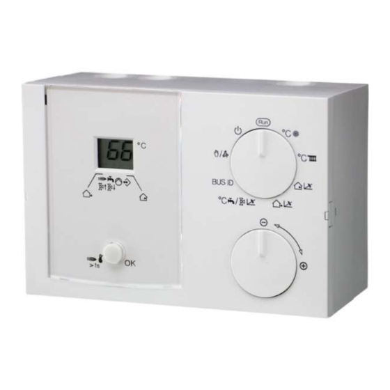
- Page 1 Lago Basic 0101/1001 Boiler module/Mixer controller Operating and Installation Instructions Please observe the safety instructions and read through this manual carefully before commissioning the equipment.
-
Page 2: General Information
Safety information General information General information Description Safety information Declaration of conformity Power connection regulations Please note the connection conditions specified by your local electrical power supply utility and the VDE regulations. Your heating control system may be installed and serviced This device corresponds to the requirements of the only by appropriately authorised specialists. -
Page 3: Table Of Contents
Description General information Functions General information Operation without operating module Safety information Control of the flow temperature Power connection regulations Mode of operation cooling Warranty conditions (only as 1001 mixer operation) Important text passages Operation using operating module Installation Zone control Description Warm-up temperature (HS min. - Page 4 Description General information System diagrams Boiler controller with direct heating circuit and Hot water Boiler controller with Header pump / mixer motor expansion Boiler controller in cascade operation Remote controls The operating module Merlin BM, BM 8, Lago FB Remote control FBR2 Sensor resistances FBR Maximum delimiter Telephone switch...
-
Page 5: Operation
Explanation of the operating elements Operation Operation Key STL-test / Enter / Reset Explanation of the operating elements STL-test (RT without effect) => By pressing > 1s Rotating switch =>Burner on, for as long as key is pressed, display:HS- Automatic mode Temp flashes (no function as mixer) To the left: Enter (modify set values) =>... -
Page 6: Display (Normal Mode "Run")
Display (normal mode "Run") Operation Display (normal mode "Run") The display shows the flow temperature of the heat generator or the heating circuit. When the incremental encoder is rotated, the following temperatures are Switch displayed: 1. Outside temperature (S, arrow 1), 9-stage 2. -
Page 7: Starting Up
Modifying set values Starting up Starting up List of the User Set Values Starting up Designation Area Factory Values After the device has been properly installed (please Run => Normal mode observe the switch position on the rear side of your Display level with shaft encoder device), switch on the power supply. -
Page 8: Explanatory Information
Set values Explanatory information The flow set temperature is increased by the set value Explanatory information Set values when the temperature drops below the required room Room set temperature temperature by 1K. => High values lead to fast control and large heat Only effective if an outside sensor or a room sensor generator temperature fluctuations. - Page 9 Set values Explanatory information Hot water set temp. (only in the case of boiler module) Flow temperature [°C] Setting the desired hot water temperature. This temperature is stabilised in the storage tank for 24h HW thermostat instead of HW sensor: Hot water preparation in the event of short circuit on the sensor input.
-
Page 10: Settings Via Dip Switch (Rear Side)
Set values Explanatory information exactly the same heating circuit numbers as the replaced never switched off before the minimum boiler temperature controller. has been reached + +5K. Parallel pump operation (F+ Settings via DIP switch (rear side) OFF => HW partial priority: The heating circuits are Switch 1-5 only valid in the case of HS controller without blocked during hot water preparation. -
Page 11: Functions
Functions Explanatory information If an outdoor sensor is connected, a weather-dependent Functions calculation of the flow set value is performed. Operation without operating module If a room sensor is connected, a room temperature When the controller is operated without an operating dependent regulation to the specified room set value is module (correspondingly, in the event of the bus activated. -
Page 12: Mode Of Operation Cooling (Only As 1001 Mixer Operation)
Functions Explanatory information Mode of operation cooling (only as 1001 mixer Warm-up temperature (HS min. – 5K) operation) Reduces operation in condensation zone. The circulation The air conditioning by the central automatic controller is pumps are switched off and the mixers are shut until the supported. -
Page 13: Dhw Relief
Functions Explanatory information are activated and the burner is enabled. Should the outdoor sensor be defective, the frost protection temperature is included in the flow calculation. DHW Relief The charging pump is not switched until the boiler temperature exceeds the storage tank temperature by 5K. It is switched off when the boiler temperature drops below the storage tank temperature. -
Page 14: Special Functions
Special functions Explanatory information Special functions EEPROM check Every 10 minutes, a check is conducted automatically in order to establish whether the settings of the controller lie within the specified limits. If a value is found to be out-of- range, it is substituted by the related default value. The range transgression is indicated by the flashing error number 81. -
Page 15: Installation
Assembly / Dismantling Installation Installation Mounting material, e.g.: Assembly / Dismantling Version 1 => Through the hole at the side Mounting holes Mounting holes, for assembly on switch box Breakthrough for leading cable through Version 2 => From the front Dimensions... -
Page 16: Electrical Connection Controller
Electrical connection Controller Installation Electrical connection Controller 230V∼; Relay switching capacity 2(2)A, 250V∼ Safety extra-low voltage 1 N-conductor, mains 11-14 CAN BUS 15-17 FBR2 2 Power supply, unit alternatively: 3 Power supply, relay 15+16 Lago switch (bridge 2 to 3) or room thermostat 4 Pump, heatcircuit / HW / 18+19 Storage tank... -
Page 17: Electrical Connection, Base
Electrical connection, base Installation Electrical connection, base Safety extra-low voltage 230V∼; Relay switching capacity 2(2)A, 250V∼ 11-14 CAN BUS 1 N-conductor, mains 15-17 FBR2 2 Power supply, unit alternatively: 3 Power supply, relay 15+16 Lago switch (bridge 2 to 3) or room thermostat 4 Pump, heatcircuit 18+19 Storage tank... -
Page 18: System Diagrams
System diagrams Installation System diagrams BUS ID: „--„ => Boiler sensor required °C : Setting of the flow temperature Boiler controller with direct heating circuit and Hot Note settings on the rear side of the controller water Heating circuit operation when: •... -
Page 19: Boiler Controller With Header Pump / Mixer Motor Expansion
System diagrams Installation Boiler controller with Header pump / mixer motor expansion... - Page 20 System diagrams Installation °C F / v Set mixer dynamics 0101 Boiler controller with collector pump In the case of weather guidance => Outside temperature BUS ID: „00„ => Boiler sensor required required Note settings on rear side of controller. °CD Set room set temperature and No heating circuit!
-
Page 21: Boiler Controller In Cascade Operation
System diagrams Installation Boiler controller in cascade operation... -
Page 22: Remote Controls
Remote controls Installation Remote controls Remote control FBR2 The operating module Merlin BM, BM 8, Lago FB The controller permits connection of an operating module via a bus line. The operation-control module allows various operation-control functions and monitoring functions for the system values to be relocated to the main controlled zone –... -
Page 23: Sensor Resistances Fbr
Remote controls Installation Installation location: All system-specific parameters can be set and interrogated • In reference / main living room of the heating circuit using the omfort oft parameterisation software. The (on an inside wall of the room). parameters can be saved, displayed graphically and •... -
Page 24: Sensors
Sensors Installation Sensors Strap-on sensor VF (VFAS) v Outside sensor AF (AFS) S Installation location: Installation location: • • In the case of boiler control instead of the boiler sensor Wherever possible, on a northerly or north-easterly KF as close as possible behind the boiler on the wall behind a heated room •... -
Page 25: Sensor Values / Characteristic Curve
Errors Installation Sensor values / characteristic curve Errors Temperature 5KOhm NTC 1KOhm PTC Ω Ω -60°C 698961 When there is an error, the corresponding error number Ω Ω -50°C 333908 flashes. Ω Ω -40°C 167835 Ω Ω -30°C 88340 Ω Ω... -
Page 26: Technical Data
Technical data Installation Technical data Supply voltage complying with 230 V AC ± 10% DIN IEC 60 038 Power consumption Max. 5 VA Switching capacity of the relays 250 V 2(2) A Maximum current on terminal 6.3 A Type of protection complying IP 40 with DIN EN 60529 Protection class complying with... - Page 28 Malfunctions due to improper operation or settings are not covered by the warranty. Kurt-Schumacher-Allee 2 · 28329 Bremen https://www.brummerhoop.com support@brummerhoop.com...
Need help?
Do you have a question about the Lago Basic 0101 and is the answer not in the manual?
Questions and answers