Table of Contents
Advertisement
Quick Links
Advertisement
Table of Contents

Subscribe to Our Youtube Channel
Summary of Contents for Turbo Econet GTA Gateway Unit
- Page 1 U s e r I n s t r u c t i o n s Econet GTA Gateway Unit Econet GTA Gateway Unit Use and Main ten ance Instructions TURBO s.r.l. InMn 38 ECOGTA Dust Filter Components en Rev.030...
-
Page 2: Table Of Contents
U s e r I n s t r u c t i o n s Econet GTA Gateway Unit Description ___________________________________________________________________________ 3 General features _____________________________________________________________________ 3 Dimensions and measurements _______________________________________________________ 4 Warnin g Symbols Used in the Manual ________________________________________________ 5... -
Page 3: Description
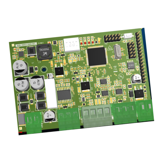
Econet GTA Gateway Unit Description The Econet GTA gateway unit (here-on indicated as gateway unit) is an electronic device to be housed on the DIN-RAIL support, able to convert the ModBus RS485 RTU commands, coming from a remote controller, on activation of valves mounted in a cleaning system that uses Turbo Econet BUS technology. -
Page 4: Dimensions And Measurements
U s e r I n s t r u c t i o n s Econet GTA Gateway Unit Dimensions and measurements Dimensions in mm TURBO s.r.l. Dust Filter Components InMn 38 ECOGTA Rev.03 en Via Po 33/35 20811 Cesano Maderno (MB) Italy Tel ++39 0362 574024 Fax ++39 0362 574092... -
Page 5: Warnin G Symbols Used In The Manual
U s e r I n s t r u c t i o n s Econet GTA Gateway Unit Warning Symb ols Used in t he Manu al The indications regarding safety are highlighted using the following symbols: Attention - Danger Warning - Generic Risk –... -
Page 6: Control Board Connection General Layout
U s e r I n s t r u c t i o n s Econet GTA Gateway Unit Control Board connection general layout Layout 1: Electric connections for Econet GTA Gateway board in BASE version. Layout 2: Electric connections for Econet GTA... -
Page 7: Configurations And Displays
U s e r I n s t r u c t i o n s Econet GTA Gateway Unit The electric connections between the circuit board of the gateway unit and the system are made using removable connectors, in order to facilitate wiring. -
Page 8: Gateway Unit Address Setting
U s e r I n s t r u c t i o n s Econet GTA Gateway Unit Gateway Unit address setting Before connecting the Gateway unit to the RS-485 RTU ModBus network, a unique device address must be set, so that the other peripherals of the same network can recognise it and manage it, thus preventing network conflicts. -
Page 9: Modbus Communication Port Configuration
U s e r I n s t r u c t i o n s Econet GTA Gateway Unit ModBus Communication Port Configuration The gateway unit uses a standard, isolated type, RS485 communication port (Physical layer), for connection to a RTU ModBus network, on which other devices are present e.g. -
Page 10: Gateway Unit Status
U s e r I n s t r u c t i o n s Econet GTA Gateway Unit Gateway Unit Status The status of the gateway control unit is available in the following ModBus registers: System status The register contains the status bits of the main functions of the gateway unit. - Page 11 U s e r I n s t r u c t i o n s Econet GTA Gateway Unit Digital inputs status The register contains the status bits of the gateway unit digital inputs. ModBus Access Data Description Default...
-
Page 12: Gateway Unit Activation Times
U s e r I n s t r u c t i o n s Econet GTA Gateway Unit Current shunt automatic calibration value The register contains the value of the actuator current shunt threshold in bit, re- calculated automatically. -
Page 13: Valves Activation
U s e r I n s t r u c t i o n s Econet GTA Gateway Unit Valves activation The valve activation modes are available in the following ModBus registers: Valve actuators to fire The following registers contain the value corresponding to the position of the valve actuator to be fired, in the chain. - Page 14 U s e r I n s t r u c t i o n s Econet GTA Gateway Unit 0x0016 RESERVED ACTUATOR_5_POS (MULTI) Reset 0x0017 RESERVED ACTUATOR_6_POS (MULTI) Reset Note: If the value of the “Actuator 1” register is set at 0 (zero) and firing mode is single, there will be no activation.
-
Page 15: Errors Management
U s e r I n s t r u c t i o n s Econet GTA Gateway Unit Actuators fire START/STOP command The following register contains the value corresponding to the START/STOP of the main power supply of the valve actuators chain. - Page 16 U s e r I n s t r u c t i o n s Econet GTA Gateway Unit Valve actuator error 1..127 The following registers contain the signalling "flags" corresponding to the error status of the valve actuators commands. In the event of activation error, the signalling flag of the corresponding valve will pass from 0 (zero) to 1.
-
Page 17: Commands Reserved For The Manufacturer
U s e r I n s t r u c t i o n s Econet GTA Gateway Unit Commands reserved for the manufacturer Current shunt threshold calibration The following register contains the factory value, in bit ADC, corresponding to the calibration of the valve actuator current shunt threshold. -
Page 18: Sequence Activation Cycle
U s e r I n s t r u c t i o n s Econet GTA Gateway Unit Sequence activation cycle All management of timing relative to the management of the cleaning cycle are under the responsibility of the monitoring system that is connected to the gateway unit. -
Page 19: Exceptio Ns
U s e r I n s t r u c t i o n s Econet GTA Gateway Unit Exception s The Actuators firing START command is not accepted if: Received during the actuator/s firing time; The firing time is not correct;... -
Page 20: Maintenance
U s e r I n s t r u c t i o n s Econet GTA Gateway Unit Maintenance The gateway unit does not have replaceable parts. All other repairs must be carried out by the manufacturer. To clean dust and dirt from the surfaces, rub delicately with cotton or another type of soft cloth soaked in a non-aggressive, non-abrasive detergent.
Need help?
Do you have a question about the Econet GTA Gateway Unit and is the answer not in the manual?
Questions and answers