Table of Contents
Advertisement
Quick Links
Advertisement
Table of Contents

Related Manuals for FläktGroup MULTIMAXX HG


Summary of Contents for FläktGroup MULTIMAXX HG
- Page 1 ® MULTIMAXX OPERATION MANUAL...
- Page 2 Multi MAXX Product range FläktGroup DC-2011-0141-GB 2021-01/R7 • Subject to modifications...
-
Page 3: Unit Type Code
Multi MAXX Unit Type Code MultiMAXX Controls Accessories 4 . U B . A O S H G 0 . E C 0 M # . # Model size Control panel, control board Model size 2 = Model size 2 0.000M Sheet steel casing Model size 2... -
Page 4: Table Of Contents
Table of Contents Multi MAXX Unit Type Code ........3 Safety and User Information . - Page 5 Multi Table of Contents MAXX Operation of the Gas Unit Heater ......50 General operation ......... . .50 Operation and adjustment of the units by means of the control panel OSHG 0.EC0M (OSHG 0.000M) .
-
Page 6: Safety And User Information
EC Directive on Machinery. MultiMAXX HG Air Heaters are safe to operate and comply with high quality standards. Future-oriented technology and pronounced operator and maintenance friendliness were combined in this product series. -
Page 7: Safety-Conscious Work Procedures
MultiMAXX HG Safety and User Information Danger due to overhead loads! This icon indicates a hazardous suspended load with a risk of personal injury includ- ing death and material damage. Danger of hot surfaces! This section specifies procedures and precautions for preventing personal injury resulting from contact with hot surfaces. -
Page 8: Proper Use
Safety and User Information MultiMAXX HG Proper use The MultiMAXX air-handling units are used in industrial, warehouse, sales and exhibition rooms, i.e., in areas which are protected against the influences of weather (including mounting, temporary storage, and maintenance work). They serve for heating, ventilation and filtration of the room/outdoor air. -
Page 9: Specifications
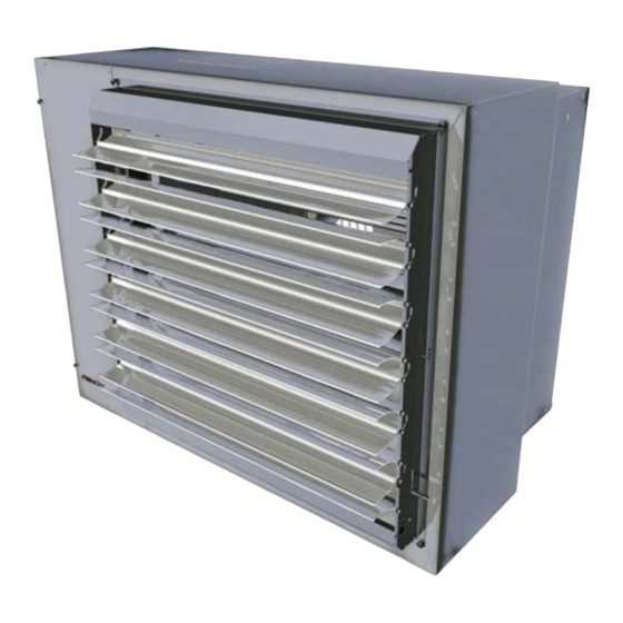
MultiMAXX HG Specifications Specifications Unit configuration and packaged content Fig. 2-1: Technical description MultiMAXX HG Pos. 1a: Wide-blade fan (optional) Pos. 7: Flue pipe fitting on air-intake side Pos. 1b: Sickle-blade fan (optional) Pos. 8: Flue pipe fitting for smoke extract Pos. -
Page 10: Specification Of Material
Specifications MultiMAXX HG Various unit parts indicated in Fig. 2-1 are specified in detail as follows. Wide-blade fan (Pos. 1a) Axial fan with external-rotor motor and integrated contact protection grille, aluminum wide blade, balanced by the manufacturer, maintenance-free with moisture proof motor wired ready for connection in the cable box. -
Page 11: Functional Description
Specifications Functional description The MultiMAXX HG Gas Air Heaters are produced in 2 model sizes with 2 capacity stages each for wall or ceiling version. The basis of the unit is formed by a coil with a robust combustion chamber and integrated retractions, assuring an optimal heat trans- fer between the combustion chamber and the air to be warmed. -
Page 12: Unit Dimensions And Minimum Installation Space
Connection of the unit to the gas mains by means of Accessories Article # ZHG.00#0 with internal screw thread R 3/4" (without accessories External thread R 1/2"- inside the unit). Fig. 2-2: Unit dimensions MultiMAXX HG Size/unit model size A [mm] 1206 B [mm] C [mm] D [mm]... -
Page 13: Technical Specifications
MultiMAXX HG Specifications Technical specifications Type Thermal Speed Airflow Burner Sound Air throw Air throw Suspen- Weight output rate Voltage Current Power con- voltage power sion height with (Blinds (Louvre U, W) range consump- sumption burner (louvre tion without C, D) -
Page 14: Commission Regulation (Eu) 2016/2281 From November 30, 2016
Specifications MultiMAXX HG Commission Regulation (EU) 2016/2281 from November 30, 2016 Values of Tab. 2-5 are intended to implement Directive 2009/125/EC of the European Parliament and of the Council establishing a framework for the setting of ecodesign requirements for energy-related products with regard to air heating products, cooling products, high temperature process chillers and fan coil units. -
Page 15: Air-Side Accessories
MultiMAXX HG Specifications Air-side accessories The following accessory items can be delivered for the MultiMAXX HG unit heater: Description Type code Model Mixed-air module, type 1 ZH#.200# Outdoor air and recirculation air offset by 90°; galvanized sheet steel, alu- minum profile blades Mixed-air module, type 2* ZH#.210#... -
Page 16: Accessories - Flue Gas Pipework, Gas Distribution
All exhaust gas conducting parts contain silicon gaskets (upon request, also seals without silicon can be delivered). Detailed information on the flue gas pipework accessories can be found in the Technical data MultiMAXX HG. The following accessory items can be supplied for the MultiMAXX HG unit heater: Description Type... - Page 17 MultiMAXX HG Specifications Description Type Dimensions - model Set with 90° T-piece D90 ZHG.6180 Diameter 80/125 mm, Al ZHG 6110 Diameter 100/150 mm, Al Set D90L ZHG.6380 Diameter 80/125 mm, Al ZHG.6310 Diameter 100/150 mm, Al Set horizontal mounting W...
-
Page 18: Shipping And Storage
Do not use damaged transport units. Air heaters can only be transported by fork lifter if they are stored on a pallet. Pay special attention to equal weight distribution! Fig. 3-1: Shipping the MultiMAXX HG unit FläktGroup DC-2011-0141-GB 2021-01/R7 • Subject to modifications... -
Page 19: Storage
MultiMAXX HG Shipping and storage Storage Protect MultiMAXX HG Air Heaters against moisture, soiling (dust and sand) and sun/ radiant heat. Store only in areas protected from weather influences, mildews, rodents, and vibrations. The air heater or control system and other accessory items must not be stored or operated... -
Page 20: Mounting
For mounting the suspension of the MultiMAXX HG Air Heaters, the following are provided 2 x 4 nut serts M8 are provided on the sides of the fan module (see Fig. -
Page 21: On-Wall Mounting
MultiMAXX HG Mounting Minimum ceiling spacing H (see Fig. 4-1) Provide a minimum distance to ceiling to allow sufficient air circulation and ensure ad- equate access for maintenance. Model size Spacing H [mm] Max. suspension height The maximum suspension height for the ceiling mounting varies depending on the dis- charge temperature, lower speed stages and lower airflow rate (results from the pressure difference of the accessory or external pressure difference). - Page 22 Mounting MultiMAXX HG Notice! For heating technology reasons, on-wall mounting of air-handling units should not be too high in order to ensure that the air is also properly mixed at ground level as well. Direction of discharged air jet Set the direction of discharge so as to prevent air draughts in the occupied zone. The primary air jet must not be directed against walls, beams, cranes, shelves, columns or similar obstacles! (see chapter 4.4)
-
Page 23: Safety Clearance
MultiMAXX HG Mounting Safety clearance Notice! When installing a heating unit, observe safety clearances of burnable materials: at least 500 mm from the unit side parts and 1500 mm in the airflow direction and the flue gas pipework. In areas with fire hazards (fire masses, dust, liquids, gases and vapors), the distance must be at least 1500 mm in all directions. -
Page 24: Mounting Examples
Mounting MultiMAXX HG 4.6.1 Maximum lengths of the flue gas pipework There must be no wall openings above the outlet of the flue gas pipework. Fig. 4-5: Length of the flue gas pipework Thermal out- Length of the flue gas pipe-... - Page 25 (ZH#.2500) or a "rectangular duct 150" (ZH#.2600). See mounting examples in Fig. 4-7 and Fig. 4-8. Notice! The installation examples given here for MultiMAXX HG Air Heaters must comply with Regulation (EU) No. 1253/2014. FläktGroup DC-2011-0141-GB 2021-01/R7 • Subject to modifications...
-
Page 26: Electrical Connection
The operator is obliged to carry out regular checks and maintenance of the electrical and gas connections in accordance with all applicable standards (see Page 61). Notice! When commissioning MultiMAXX HG air-handling units, the safety regulations and standards and generally approved technical practice applicable in the respective countries must be observed. Notice! The electrical connection must be carried out with an all-pole separator with a con- tact breaker gap of min. -
Page 27: Electric Switch Cabinet
The connection diagrams do not specify any protective measures. 5.2.1 Motor contactor using thermal contact The fans of the MultiMAXX HG Air Heaters are equipped with thermal contacts as stan- dard, which must always be connected. No warranty can be assumed if other on-site fuse protection of the fan are used. - Page 28 Electrical Connection MultiMAXX HG 5.3.1 Control panel OSHG 0.EC0M (OSHG 0.000M) - Control system for a unit group (1 to 10 units) Fig. 5-2: Control panel OSHG 0.EC0M (OSHG 0.000M) For Multi Operation, the electric switch cabinet is mounted on site to the air heater. Up to 10 units can be controlled with one control panel OSHG 0.000M...
- Page 29 MultiMAXX HG Electrical Connection 5.3.3 Connection diagram of MultiMAXX HG units (fans D, E, Y - 1 x 230 V/50 Hz) with control panel OSHG 0.EC0M (OSHG 0.000M) (Multi Operation) or remote control controller PCB OSHG 0.RDDO O Fig. 5-4: Controller PCB FläktGroup DC-2011-0141-GB 2020-05/R6 •...
- Page 30 Electrical Connection MultiMAXX HG Fig. 5-5: Controller PCB FläktGroup DC-2011-0141-GB 2020-05/R6 • Subject to modifications...
- Page 31 MultiMAXX HG Electrical Connection Secondary fuse Primary fuse Fig. 5-6: Controller PCB FläktGroup DC-2011-0141-GB 2020-05/R6 • Subject to modifications...
- Page 32 Electrical Connection MultiMAXX HG Fig. 5-7: Controller PCB FläktGroup DC-2011-0141-GB 2020-05/R6 • Subject to modifications...
- Page 33 MultiMAXX HG Electrical Connection Fig. 5-8: Controller PCB FläktGroup DC-2011-0141-GB 2020-05/R6 • Subject to modifications...
-
Page 34: Gas Connection
Gas installation may only are carried out by trained gas workers observing valid building codes. Notice! When commissioning MultiMAXX HG air-handling units, the safety regulations and standards and generally approved technical practice applicable in the respective countries must be observed. - Page 35 MultiMAXX HG Gas Connection Danger of accident due to gas explosion! The connection diagram contains no safety precautions. These must be ensured for the installation of the unit. Connection of the Pressure hose internal screw thread R 3/4" + unit to the gas reducer with external screw thread R 1/2"...
-
Page 36: Commissioning
(see Page 68). Notice! When commissioning MultiMAXX HG air-handling units, the safety regulations and standards and generally approved technical practice applicable in the respective countries must be observed. - Page 37 MultiMAXX HG Commissioning – The setting of the main control element in the main gas distribution corresponds to the value ˃ 3 kPa, so that the operating pressure according to chapter 2.4 is secured on all units. If controllers are installed upstream of each unit, the gas pressure in the main distribution system shall not exceed the value permitted by the manufacturer of the controller.
- Page 38 Commissioning MultiMAXX HG Pos.1: Screw (V1) for changing the minimum gas flow rate of the burner Pos.2: Screw (V2) for changing the maximum gas flow rate of the burner Pos.3: Test point of the gas pres- sure in the inlet (P1) Pos.4:...
- Page 39 MultiMAXX HG Commissioning The V2 gas valve is covered with a metal cap! Only use a T40 bit to set the V2 valve. The screw is made of plastic and can be damaged if an unsuitable tool is used! The settling time of the values after changing the setting is min. 10 minutes.
- Page 40 Commissioning MultiMAXX HG Unit type Gas burner type Gas type Trimmer Gas burner fan Burner speed efficiency Designation Orientation [kW] setting 2600 4250 START 3600 HG 24 2400 LPG* 4000 START 3400 RX 35 3500 5100 START 4100 HG 25...
- Page 41 MultiMAXX HG Commissioning thermal output. If the temperature difference (setpoint/actual temperature) is Tp +1°C (22°C), then for the recirculating-air unit (HG##.U#####.### ), the gas burner and fan of the unit is switched off; for the mixed-air unit (HG##.M#####.### ) only the gas burner is switched off - the fan of the unit continues to run.
- Page 42 Commissioning MultiMAXX HG Changeover Function Changeover switch position switch no. OFF (0) ON (1) Control According to room temperature According to supply-air temperature of the thermal out- (HG##.###T##.### ) (HG##.###P##.### ) Set temperature Only the burner switches off The burner and fan of the unit switch off...
- Page 43 MultiMAXX HG Commissioning If the control is set: – After the room temperature (OFF) - the burner switches off after reaching the tem- perature set on the room thermostat or after reaching the temperature +1°C (sensed by an internal or external room temperature sensor) - first the thermal output of the unit is reduced by the minimum set by the control.
- Page 44 Commissioning MultiMAXX HG Changeover switch no. 9-12 Setting the unit addresses - ON(1), OFF(0) see Tab. 7-4 Connection of the terminal pins and their combinations Unit Changeover Changeover Changeover Changeover number switch no. 12 switch no. 11 switch no. 10 switch no.
- Page 45 MultiMAXX HG Commissioning 7.1.4.3 Setting the air pressure drop (control according to supply-air temperature) Control panel OSHG 0.EC0M (OSHG 0.000M) - Multi Operation (only for mixed-air units) To set the pressure loss of the mixed air units, proceed as described in chapter 8.3 and Fig.
- Page 46 Commissioning MultiMAXX HG If the output voltage drops to 0 V, this is an error: 01 - Burner error 02 - Fan TC error 03 - Coil sensor error 04 - Dirty filter 5 V - No current load possible (signal output resistance 10 k ) - Connect a system with a large input resistance (min.
- Page 47 MultiMAXX HG Commissioning Changeover switch no. 9 In the OFF position, the affected unit number is displayed in the event of a fault Number is displayed. In the ON position, the exact burner capacity value set with the trimmer is displayed.
- Page 48 Commissioning MultiMAXX HG Changeover switch Changeover switch Changeover switch Air outlet Air outlet Air outlet setting setting setting tempera- tempera- tempera- ture °C ture °C ture °C Tab. 7-7: Temperature switch combinations 7.1.5.3 Setting the burner output on the remote control controller PCB The desired burner capacity is set by means of a trimmer for the whole section 0-10 (0- 100%) (see Fig.
- Page 49 MultiMAXX HG Commissioning Light-emitting Designation Alarm signal diode (LED) HOR S3 Burner Fan thermal contacts PT HX Coil temperature sensor FILTR Dirty filter HOR SET Incorrectly adjusted burner PT VK Temperature sensor in the fan chamber (PT1000) There is no communication between the unit and the remote control controller PCB COMM OSHG 0.RDDO...
-
Page 50: Operation Of The Gas Unit Heater
Operation of the Gas Unit Heater MultiMAXX HG Operation of the Gas Unit Heater General operation Before switching on the unit, please check the opening of the gas shut-off valve and control gear of the electric current supply. First, the following parameters must be set on the OSHG 0.EC0M (OSHG 0.000M) control panel: –... - Page 51 MultiMAXX HG Operation of the Gas Unit Heater Operating part of the control panel Key (Symbol) Function After pressing the ENTER key for longer than 5 sec, the complete group of units is switched on or off. At the same time, this key is used to confirm selected menu items.
- Page 52 Operation of the Gas Unit Heater MultiMAXX HG 8.2.1 SETUP menu Notice! In order to open or close the SETUP menu, press the keys ESC and UP for at least 5 sec. Representation of the SETUP MENU for the OSHG 0.000M control panel (see Fig. 8-...
- Page 53 MultiMAXX HG Operation of the Gas Unit Heater Symbol MENU MENU display on the control panel Setting options Number of Number of units in one control units group Pressure drop Number of the unit for which for which the pressure loss (only for sup- is set.
- Page 54 Operation of the Gas Unit Heater MultiMAXX HG Symbol MENU MENU display on the control panel Setting options Display of the Information about the control control panel panel parameters 1.48 FW model of the control panel 21.0 Room temperature measured...
- Page 55 MultiMAXX HG Operation of the Gas Unit Heater 8.2.2.1 Main menu In the main menu, the desired temperature is adjusted in steps of 0.5 K. Symbol Function In order to cancel the key lock, press the ESC key longer than 3 sec.
- Page 56 Operation of the Gas Unit Heater MultiMAXX HG 8.2.2.3 Unit menu (and other submenus) The submenu is selected in the Unit menu with the setting keys. The ENTER key confirms the action and enters into the submenu. The entered values in the submenus are confirmed with the ENTER key.
- Page 57 MultiMAXX HG Operation of the Gas Unit Heater Symbol MENU MENU display on the control panel Setting options Adjust the air Increase the air outlet angle outlet angle Decrease the air outlet angle Unit RESET of the selected unit RESET...
- Page 58 Operation of the Gas Unit Heater MultiMAXX HG 8.2.3.1 Main menu Symbol Function In order to cancel the key lock, press the ESC key longer than 3 sec. The specified unit operates without interference A fault has occurred on the specified unit or no data connection is available.
-
Page 59: Adjustment Of The Mixed-Air Module
MultiMAXX HG Operation of the Gas Unit Heater Symbol MENU MENU display on the control panel Setting options Setting the fan Fan switched off speeds Fan speed 1 Fan speed 2 Fan speed 3 Adjustment of the outdoor-air rate from 0 to 100% in steps... -
Page 60: Differential Pressure Switch
Operation of the Gas Unit Heater MultiMAXX HG The actuator with potentiometer can be used to control the secondary air louvre (only in the case that no mixed air chamber is built on the unit or the control is performed outside the Multi control). -
Page 61: Maintenance
Explosions and fire can occur through escaped gas. Danger of damage due to static discharge! When connecting and/or adjusting MultiMAXX HG air-handling units, be sure to dis- charge any static electricity before touching the PCB and electrical components. Danger of hot surfaces! -
Page 62: Quarterly Maintenance
Maintenance MultiMAXX HG Quarterly maintenance 9.2.1 Replacing filter If an air-handling unit is fitted with a filter module, the filter insert must be checked for clean condition. If there is a maximum pressure drop as defined by the project, the filter insert must be replaced. -
Page 63: Semi-Annual Maintenance
MultiMAXX HG Maintenance Pos. 1: Filter chamber Pos. 2: Mat filter G2,G3 or G4 Unlock the side panel of the filter section (1) by slightly turning quick-action clamps by 90° and remove the filter. Pull out the mat filter insert and replace it (2). -
Page 64: Annual Maintenance
Maintenance MultiMAXX HG 9.3.5 Check coil Any contaminations of the coil must be removed. The contaminated coil can be cleaned with compressed air. No other parts may be damaged during cleaning. Unit damage! When cleaning with a water jet, do not direct it at the fan motor, burner or other elec- trical parts;... -
Page 65: Breakdowns
MultiMAXX HG Maintenance Breakdowns Symptom Possible cause Troubleshooting Fan does not work Unit not switched on Switch on unit Valve gate switch is switched on. No mains voltage Check fuse/circuit breaker/power supply On the OSHC 0.000M control panel, the (technical personnel only) unit number is not underlined but crossed out. - Page 66 Maintenance MultiMAXX HG Symptom Possible cause Troubleshooting Jednotka je v poruchovém stavu Nízká teplota výměníku. Zanesené vnitřní Prověřte teplotu výměníku při hoření na plný sítko hořáku, nebo špatně nastavený výkon. Pokud je teplota výměníku pod 60°C, výkon hořáku. zkontrolujte jonizační proud hořáku, otáčky ventilátoru hořáku, obsah spalin...
-
Page 67: 10 Disassembly And Disposal
Secure the unit against slipping. The unit is ready for transport. 10.2 Recycling Recycling! The disposal of MultiMAXX HG units or individual components must be carried out by an authorized appointed contractor with the necessary expertise. The appointed contractor must ensure that: •... -
Page 68: 11 Warranty Conditions
11.1 Authorized service companies for warranty and repairs in Germany Warranty and repair service for MultiMAXX HG gas heater units must be performed by the same company that performed the installation. FläktGroup DC-2011-0141-GB 2021-01/R7 • Subject to modifications... -
Page 69: 11.2 Warranty Certificate
Date, stamp of the company and signature For service requirements, the manufacturer (together with the order or complaint report) requires a copy of the completed warranty certificate (type and identification number of the MultiMAXX HG unit and the burner). FläktGroup DC-2011-0141-GB 2021-01/R7 • Subject to modifications... - Page 71 MultiMAXX HG FläktGroup DC-2011-0141-GB 2021-01/R7 • Subject to modifications...
- Page 72 WWW.FLAKTGROUP.COM MULTIMAXX HG FläktGroup is the European market leader for smart and energy efficient Indoor Air and Critical Air solutions to support every application area. We offer our customers innovative technologies, high quality and outstanding performance supported by more than a century of accumulated industry experience. The widest product range in the market, and strong market presence in 65 countries worldwide, guarantee that we are always by your side, ready to deliver Excellence in Solutions.
Need help?
Do you have a question about the MULTIMAXX HG and is the answer not in the manual?
Questions and answers