Table of Contents
Advertisement
Quick Links
Advertisement
Table of Contents

Summary of Contents for Forenex MBE71
- Page 1 MBE71 User MBE71 Manual Motherboard User Manual (Preliminary) with Dual Cortex-A72 @2.0Ghz + Quad Cortex-A53 @ 1.5Ghz Core Version: V3.0 Document No: doc-mbe7118w40v30 PCB Bare Board: PB71m68v11 *The content of this document is subject to be change without notice...
- Page 2 MBE71 User Packing List Manual 1 x MBE71 Motherboard. Ordering Information Part Number: MBE71-abcxyMN HDMI 2.0, eDP1.3 (2xlane), GigE, 5G-Wifi with mPCIE Socket, OTG-USB 3.0 (Type- A), USB2.0 (Type-A), Micro-SD Socket, Grove GPIOs, Reset CONN, Optic Fiber CONN, 4- wire UART Port, IR Port, Debug Port, Audio, USB-Hub, DC-Jack.
- Page 3 MBE71 User Revision histories Manual Rev. No. Date Substantial Changes 2021/01 First issue.
-
Page 4: Table Of Contents
MBE71 User Table of Contents Manual General Information ......................6 1-1. Features ..........................6 1-2. Function Block Diagram ......................8 1-3. Board Dimension ........................9 1-4. I/O Connector Summary ......................9 1-5. I/O Connector Placement ....................10 Peripherals Port Description ..................... 11 2-1. - Page 5 MBE71 User 2-22. USB host2.0, MEMS signals Combo Connector (W10) ............19 Manual 2-23. HUB Extended Ports (W8, W9, W18) ................... 19 2-24. Audio Codec Interface (H10) ....................20 2-25. mini-PCIe Slot(J9) ......................... 21 2-26. MIPI-CSI Interface (W13) (Optional) ,Under development..........22 Software Programming Guide ..................
-
Page 6: General Information
Besides, the high-performance media-processor also especially for infotainment/entertainment, HMI applications. The heart of the MBE71 is the Dual Cortex-A72 @2.0Ghz + Quad Cortex-A53 @ 1.5Ghz processor, which provides a complete platform for project evaluation and solution feasibility testing that decreases the time to market and lowers initial cost. - Page 7 MBE71 User Audio: Manual Realtek ALC5640 low power stereo codec Inside Stereo Class-D speaker amplifiers provide 1.5W per channel into 8Ω or 2W per channel into 4Ω LAN: Realtek RTL8211E Gigabit Ethernet transceiver with RGMII support Extension USB device: ...
-
Page 8: Function Block Diagram
MBE71 User 1-2. Function Block Diagram Manual... -
Page 9: Board Dimension
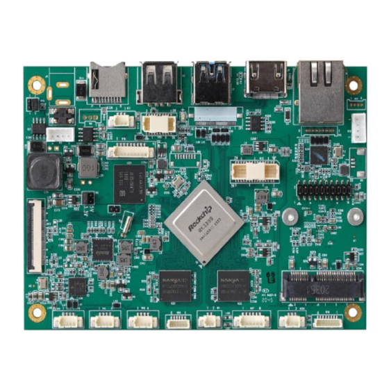
MBE71 User 1-3. Board Dimension Manual Dimension: 126.5mm (W) x 90mm (L) x 18.7mm (H) Contact Service salesman for detail “.DXF” file. 1-4. I/O Connector Summary External I/O (On board side): Power Jack (J4),(W4) Micro SD Socket (J1) ... -
Page 10: I/O Connector Placement
MBE71 User 1-5. I/O Connector Placement Manual Component Side Solder Side -10-... -
Page 11: Peripherals Port Description
Pin1 Pin2 DC12V 2-2. Power Switch, Header (H15) Shorts the Pin 1&2 of the H15, to power up MBE71 mainboard. The Pin 3 & 4 of the H15 reserved. Connector: (Header 2x2 pin/ 2.0mm/ 180°) Pin number Status... -
Page 12: Ir Receiver Connector (Ir1)
MBE71 User 2-4. IR Receiver Connector (IR1) Manual Connects an external IR-38.8Khz receiver module Pin Assignment: Connector: (wafer-3P/ 1.25mm/ 180°) Pin number Description IR Signal input(1k ohm of Series resistor inside) 3.3V supply 2-5. Power LED Connector (W7) ... -
Page 13: Usb 3.0 Type-A Port (J2)
2-7. USB 3.0 Type-A Port (J2) Manual The dedicated USB port to in charge of updating the Image File while the MBE71 board being enter update mode. Refer to Section 2-6. Under Linux OS environment, the J2 is regarded as an USB3.0 host. And gives complete hot plug capability and complies with USB xHCI, Rev. -
Page 14: Gigabit Ethernet Port W/Poe+ (J6)
MBE71 User 2-9. Gigabit Ethernet Port w/PoE+ (J6) Manual The integrated 8-pin Gigabit Ethernet port is using an 8 Position 8 Contact (8P8C) receptacle connector (commonly referred to as RJ-45). Supports IEEE802.3 at compliant (type2) PD. The Gigabit Ethernet port (RJ-45 port) has two individual LED indicators located on the front side to show ... -
Page 15: Edp Interface (Zif2)
MBE71 User 2-13. eDP Interface (ZIF2) Manual Supports eDP 1.3(2.7Gbps per lane). 4 Lane with connector A1253WR-S-40P is defaulted in factory. Supports 2 Lane, Res. up to1920x1200p@60fps with connector A1253WR-S-30P. Supports 4 Lane, Res. up to2560x1600p@60fpswith connector A1253WR-S-40P. -
Page 16: Lcd Panel Power Selection (H2)
MBE71 User 2-14. LCD Panel Power Selection (H2) Manual Provides 3.3V to LCD_VDD Provides 5V to LCD_VDD 2-15. LCD Backlight Control Connector (W2) The voltage of BL_VDD is same as DC_IN, due to the power source of BL_VDD is passed from DC-in Jack (J4) or (W4) directly. -
Page 17: Hdmi® 2.0 Port (J5)
MBE71 User 2-17. HDMI® 2.0 Port (J5) Manual The HDMI port uses an HDMI Type-A receptacle connector. It allows connecting the digital video devices which utilize a high definition video signal without a HDCP. Supports HDMI® V2.0, Res. up to 4Kx2K(30-bit/pixel) @60fps, HDCP1.4 /2.2 ... -
Page 18: Rs232 Debug Connector (W20)
MBE71 User 2-19. RS232 Debug Connector (W20) Manual The debug port supports TX/RX with RS232 level and only use for debug purpose. Pin Assignment: Connector: ( wafer-3P/ 1.25mm/ 180° ) Pin number Description Debug-RS232-RX(SIN) Debug-RS232-TX(SOUT) COM_GND 2-20. Grove-I2C,SPI,ADC,GPIOs Connector (W15) ... -
Page 19: Usb Host2.0, Mems Signals Combo Connector (W10)
MBE71 User Manual 2-22. USB host2.0, MEMS signals Combo Connector (W10) The connector (W10) can be either used as an extra USB 2.0 individually. Or use for a LTE 4G modem module application. Or use for a USB-MEMS application. -
Page 20: Audio Codec Interface (H10)
MBE71 User 2-24. Audio Codec Interface (H10) Manual Supports speaker amplifiers 1.5W per channel into 8Ω or 2W per channel into 4Ω. Pin Assignment: Connector: (Header 2x10 pin/ 2.0mm/ 180° ) Description Description HP_R MIC_IN HP_L HP_GND HP Plug-in detection, (3.3V)high active... -
Page 21: Mini-Pcie Slot(J9)
MBE71 User 2-25. mini-PCIe Slot(J9) Manual Reserved for 5G/ Dual Band Wi-Fi module, AP12356,802.11 a/b/g/n/ac(2T2R) + BT(V4.1 LE), mPCIe interface. in Assignment: Connector: ( 88910-5204M/ 2X26p/ MINI PCI EXPRESS) Pin number Description Pin number Description PCIe_Wake# 3.3V 1.5V... -
Page 22: Mipi-Csi Interface (W13) (Optional) ,Under Development
MBE71 User 2-26. MIPI-CSI Interface (W13) ,Under development. (Optional) Manual Supports 4 Lane, (1.5Gbps per lane). Pin Assignment: Connector: (TFP618-15P/ 1.0mm/ 180°) Pin number Description Pin number Description DC-5V DC-1.8V DC-5V DC-1.8V DC-5V BL-PWM DC-3.3V BL-EN DC-3.3V MIPI_RST... -
Page 23: Software Programming Guide
MBE71 User 3. Software Programming Guide Manual 3-1. Android Programming Guide 3-1-1. ADB installation Originally, the USB3.0 was defaulted as host mode. Before use function ADB, the USB 3.0 Port have to be set to device mode by following steps. - Page 24 MBE71 User Step3. After finished above action, a new item "Developer Options" will appear Manual in the system block. Step4. Get into the new item "Developer Options" and turn on the USB debugging function. Note: Please do not change the others that you do not understand what it does.
-
Page 25: To Install Apk Software Over The Adb Function Of Pc
MBE71 User Manual ● Then Scroll to "USB > ADB/HOST" ● Set USB3.0 as ADB 3-1-2. To install APK software over the ADB function of PC : Complete the connectivity between USB3.0 (Type A) port of MBE70 and USB port of PC. -
Page 26: Linux Programming Guide
MBE71 User port. Manual 3-2. Linux Programming Guide 3-2-1. GPIO installation GPIOs definition Position PIN name Linux node/Note Direction PIN 1 DIN2 /sys/class/gpio/gpio76/value In PIN 2 DOUT2 /sys/class/gpio/gpio69/value Out PIN 3 DIN0 /sys/class/gpio/gpio74/value In PIN 4 DOUT1 /sys/class/gpio/gpio68/value Out...
Need help?
Do you have a question about the MBE71 and is the answer not in the manual?
Questions and answers