
Summary of Contents for TOPVISION PN8602-G OLT
- Page 1 PN8602-G OLT Hardware Description TOPVISION TECHNOLOGIES CO., LTD. http://en.sumavision.com/ Issue: R01 Date: June 2018...
- Page 2 Statement Copyright © 2001-2018 Topvision Technologies Co., Ltd. of Sumavision Technologies Group. All rights reserved. Without the written permission of the Company, any units or individuals are not allowed to extract, reproduce any part or all of this Manual, and shall not transmit in any form.
- Page 3 Version Control Date Revision Description 2018.06 Release...
-
Page 4: Foreword
OLT device. Manual Introduction PN8602-G OLT Hardware Description describes the hardware composition, structure, and features of the PN8602 series OLTs. This manual contains the following chapters: Chapter 1 Overview describes the exterior, external ports, indicators, product configuration, parameters, basic principles, power supply principle, heat dissipation principle, dust-proof design, and labels of the PN8602-G. - Page 5 Danger — Danger indicates that the described activity or situation may result in serious personal injury or death, for example, high voltage or electric shock hazards. Warning — Warning indicates that the described activity or situation may, or will, cause equipment damage or serious performance problems.
-
Page 7: Table Of Contents
Table of Contents Foreword ............................IV Table of Contents ..........................I Figures ............................... II Tables ..............................III Chapter 1 PN8602-G Overview ....................1-1 Exterior ..........................1-1 External Ports and Indicators ....................1-1 Product Configuration ......................1-5 Parameters ........................... 1-5 Basic Principles ........................1-6 Power Supply Principle ...................... -
Page 8: Figures
Figures Figure 1.1-1 PN8602-G-8 ......................... 1-1 Figure 1.1-2 PN8602-G-16 ........................1-1 Figure 1.2-1 External ports on the front panel of the PN8602-G-8 ............1-2 Figure 1.2-2 External ports on the front panel of the PN8602-G-16 ............1-2 Figure 1.2-3 Indicators on the front panel of the PN8602-G-8 ............... 1-3 Figure 1.2-4 Indicators on the front panel of the PN8602-G-16 ............. - Page 9 Tables Table 1.2-1 Description of external ports on the front panels of the PN8602-G-8 and PN8602-G-16 ... 1-2 Table 1.2-2 Description of indicators on the front panels of the PN8602-G-8 and PN8602-G-16 ..1-3 Table 1.2-3 Description of ports on the rear panels of the PN8602-G-8 and PN8602-G-16 ....1-4 Table 1.2-4 Description of indicators on the rear panels of the PN8602-G-8 and PN8602-G-16 ...
-
Page 11: Chapter 1 Pn8602-G Overview
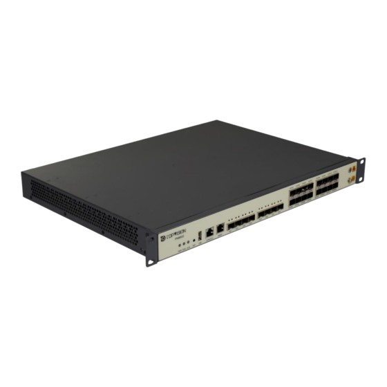
Chapter 1 PN8602-G Overview PN8602-G is a 1U box-shaped device that adopts the fixed line cards. It can accommodate up to 8 10G uplink ports and 16 GPON ports. The fan is fixed on the left side of the box and adopts the induced draft ventilation mode. - Page 12 PN8602-G OLT Hardware Description Figure 1.2-1 External ports on the front panel of the PN8602-G-8 The following figure shows the external ports on the front panel of the PN8602-G-16. The ports are described in Table 1.2-1. Figure 1.2-2 External ports on the front panel of the PN8602-G-16 Table 1.2-1 Description of external ports on the front panels of the PN8602-G-8 and PN8602-G-16...
- Page 13 Chapter 1 PN8602-G Overview Port Silk Screen Quantity Function Description Reset button Hardware reset, used to restart the device The following figure shows the indicators on the front panel of the PN8602-G-8. The indicators are described inTable 1.2-2. Figure 1.2-3 Indicators on the front panel of the PN8602-G-8 The following figure shows the indicators on the front panel of the PN8602-G-16.
- Page 14 PN8602-G OLT Hardware Description Silk Screen LED Color State Description No alarm exists. MGMT Yellow Always on The rate of the current management port is 100Base-TX. The current management port is 10Base-T, or is not connected. Green Always on The current management port is connected. (Link)
-
Page 15: Product Configuration
Chapter 1 PN8602-G Overview Button Silk Screen Quantity Description Power button ON/OFF Press ON to turn on the power module and power on the device. Press OFF to shut down the power module and power off the device. 1.3 Product Configuration Table 1.3-1 PN8602-G product configurations Product Model Main Board Model... -
Page 16: Basic Principles
PN8602-G OLT Hardware Description Power supply: 220V AC Room temperature 25°C Static power consumption: Power consumption when device is powered with no loading Maximum power consumption: When device is powered and all service slots are filled Table 1.4-2 PN8602-G power supply parameters... -
Page 17: Heat Dissipation Principle
Chapter 1 PN8602-G Overview Figure 1.6-1 AC power distribution principle of the PN8602-G 1.7 Heat Dissipation Principle This section describes the heat dissipation principle of the PN8602-G. Ventilation process for the chassis: The cold air enters the chassis from the left side of the chassis, reaches the main board radiator after being circulated by the fans, and is finally discharged from the left side of the chassis. -
Page 18: Device Labels
1.9 Device Labels Serial Number Label The serial number label is the unique No. of a Topvision product, and used for the after-sales service. This label is attached to the rear panel of the PN8602-G. The serial number is a 17-digit number, as shown in the following figure. -
Page 19: Figure 1.9-2 Mac Address Label
Chapter 1 PN8602-G Overview Symbol Meaning Explanation YYMM Date of YY: year; MM: month Manufacture AAAAAABBB Product AAAAAA: model of the product or line card. For example, "PN8602" indicates a Model PN8602 series product, and "PNMPUA" indicates the MPUA line card. BBB: sub-specification code. -
Page 21: Chapter 2 Pluggable Module
Chapter 2 Pluggable Module About this Chapter This chapter describes the pluggable module types and parameters, and the corresponding relationships with the line cards. The optical module packages supported by the company’s line card devices include SFP, SFP+ and XFP, and the supported interface types are LC, SC, RJ-45 (electrical module). The various optical modules are shown in the following table. -
Page 22: Table 2.1-2 Parameters Of The Bidirectional Single Fiber Ge Optical Module
PN8602-G OLT Hardware Description Working center 850nm 1310nm 1310nm 1550nm 1550nm wavelength Package form Speed rate 1.25Gb/s 1.25Gb/s 1.25Gb/s 1.25Gb/s 1.25Gb/s Optical connector type Fiber type Multimode Single mode Single mode Single mode Single mode Transmission distance 0.5km 20km 40km... -
Page 23: 10Ge Optical Module
Chapter 2 Pluggable Module 2.2 10GE Optical Module This section introduces the 10GE optical module types and parameters, and its corresponding relationship with the line cards. 10GE Optical Module (SFP+) The 10GE optical module (SFP+) connects to two LC optical fibers to create a single channel 10GE. The parameters are shown in the following table. - Page 24 PN8602-G OLT Hardware Description Optical connector type Fiber type Single mode Single mode Saturated light power -8 dBm -8 dBm Tx optical power 1.5~5 range (dBm) Rx optical power -28~-8 -32~-12 range (dBm) 2-14...
-
Page 25: Chapter 3 Cable
Chapter 3 Cable About this Chapter This chapter mainly introduces the cables that the device requires, including a view of the physical cables, the connections, applications and technical parameters. 3.1 Power Supply Cable and Ground Wiring The power supply cable refers to the electrical cables used to provide electric power to enable the chassis to function normally. -
Page 26: Pgnd Cable
PN8602-G OLT Hardware Description Figure 3.1-2 Different Standards of Power Cable Table 3.1-1 Specifications of National Standard Power Cable National Parameters Specifications European Terminal type Type F : Black extended pin (D2-02)/European standard (2 round) American Terminal type Type B:Black extended pin (D2-02)/American... -
Page 27: Serial Cable For Local Maintenance
Chapter 3 Cable Parameter Description Type of electrical cable Electronic power cable DC resistance of the internal conductor 0.78Ω/km Maximum current 110A Conductor cross-section area 3.2 Serial Cable for Local Maintenance The serial cable is used for device debugging or to perform local maintenance on the device. Applications The serial cable is used for debugging or to perform local maintenance. -
Page 28: Network Cable
PN8602-G OLT Hardware Description Parameter Description Connector type DB9 female + 8-pin network port/DB25 female Type of electrical cable Symmetric twisted pair cable Diameter of the inner conductor 0.38mm Wire gauge of the inner conductor 28AWG (cross-sectional area ≈ 0.08mm... -
Page 29: Figure 3.3-1 Network Cable
Chapter 3 Cable Figure 3.3-1 Network cable The structure of the network cable is shown in the following figure. Figure 3.3-2 Structural view of a network cable Connections The connections of a straight-through cable are shown in the following table. Table 3.3-1 Connections for a straight-through network cable X1 pin Core line color... -
Page 30: Optical Fiber
PN8602-G OLT Hardware Description X1 pin Core line color X2 pin Orange White and green Blue White and blue Green White and brown Brown Technical Parameters The following table shows the technical parameters of the network cables. Table 3.3-3 Technical parameters of network cables... -
Page 31: Figure 3.4-1 External View Of A Single Mode Optical Fiber With The Lc/Pc Type Connector
Chapter 3 Cable from several hundred meters to several kilometers. A single-mode fiber is generally in yellow and marked as "SM". Single-mode fibers often work at about 1310nm to 1550nm, the transmission loss is about 0.2 to 0.3dB/Km, and the transmission distance often exceeds 10 kilometers. -
Page 32: Table 3.4-1 Selection Criteria For Optical Fibers
PN8602-G OLT Hardware Description Optical fiber selection is based on the following table. The common optical connectors are shown below. Table 3.4-1 Selection criteria for optical fibers Parameter Selection criteria Length Survey results Single mode/multimode Type of optical module Square connectors: SC/PC, SC/APC, LC/PC... -
Page 33: Annex 1 Abbreviations
Annex 1 Abbreviations Automatic Gain Control Automatic Power Control Angle Physical Contact EPON Ethernet Passive Optical Network Ferrule Connector FTTB Fiber To The Building FTTC Fiber To The Curb FTTH Fiber To The Home FTTO Fiber to the Office FTTW Fiber To The Wlan GPON Encapsulation Method GPON...
Need help?
Do you have a question about the PN8602-G OLT and is the answer not in the manual?
Questions and answers