Table of Contents
Advertisement
Quick Links
Guardian Controls International Ltd
1
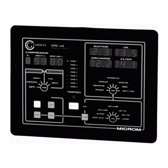
GUARDIAN RCC-50
Reciprocating Compressor Controller
• Single-stage or Dual-stage Reciprocating compressor controller
• Pressure, temperature, capacity% and load% displays
• Suction pressure setpoint control of up to 4 capacity loading valves
• Alarm and trip monitoring
• Multiple pack/compressor system control
• Local panel operation and set-up of pack configuration & control modes
• Communications for remote monitoring and set-up
Operation and Setup Manual
The GUARDIAN RCC-50 Compressor Pack Controller provides suction pressure setpoint
control and alarm monitoring for either a single-stage or a dual-stage large industrial
reciprocating compressor with up to 4 loading valves.
GUARDIAN RCC-50
Issue V1.0 a 25/09/06
Advertisement
Table of Contents

Related Manuals for Guardian Controls International RCC-50

Summary of Contents for Guardian Controls International RCC-50
-
Page 1: Guardian Rcc-50
• Communications for remote monitoring and set-up Operation and Setup Manual The GUARDIAN RCC-50 Compressor Pack Controller provides suction pressure setpoint control and alarm monitoring for either a single-stage or a dual-stage large industrial reciprocating compressor with up to 4 loading valves. -
Page 2: Table Of Contents
RCC50 Fuse Ratings ...................... 12 RCC50 FUSES and LED LAYOUT ................. 13 RCC-50 Termination Wiring - SSrL model selection............14 RCC-50 Termination Wiring - dSrL model selection ............15 OPERATION ..................16 RCC-50 PANEL LAYOUT ....................16 CONTROL STATUS LED LAMPS .................. 16 LED LAMPS. - Page 3 Suction Group Control Communications................ 40 Setup / Commissioning Parameters ................41 Settings display and change facilities................43 RCC-50 Enclosure wiring: for trips negative ..............45 RCC-50 Enclosure wiring: for trips positive..............46 FITTING NEW EPROM ................47 CORRECT POSITIONING OF EPROM ALIGN INDICATED INDENTS......47 Index ..........................
-
Page 4: Getting Started
Guardian Controls International Ltd GETTING STARTED Guardian Controllers provide refrigeration engineers with • ULTIMATE FLEXIBILITY • ASSURED MONITORING • RELIABLE ALARMS This manual provides refrigeration designers, installers, service mechanics and supermarket personnel with the necessary information to achieve the above objectives. -
Page 5: Button Operation Shorthand
Guardian Controls International Ltd BUTTON OPERATION SHORTHAND To assist in easy set-up of control setpoints, delays, timers and other configuration settings, the sequence of button presses and subsequent displays will be shown in this handbook as below: “@ ” A button symbol, followed by text means press that button. -
Page 6: Configure Unit Model, System No & Address
Guardian Controls International Ltd CONFIGURE UNIT MODEL, SYSTEM No & ADDRESS Enter Passcode Before any permanent change of controller settings are made then the correct entry of the appropriate passcode is necessary. The settings available for change on each passcode are as follows;... -
Page 7: Select System No And Address
Guardian Controls International Ltd Select System No and Address e.g. setup unit for system 65 compressor number 1 at address 195 Enter setup as button sequence as above SUCTION OIL1 ==sE tUP= DISCHARGE OIL2 ==== =yEs “@ ” accept DISCHARGE... -
Page 8: Unit Models
OVERVIEW Functions The GUARDIAN RCC-50 controller provides facilities for:- MONITORING Measurement of 5 pressures and 5 temperatures and pack load for control, alarm and trip display. -
Page 9: Displays
In LOCAL automatic mode, the compressor is started and stopped under control of the suction pressure setpoint. REMOTE automatic mode allows up to six RCC-50 units to be connected via a two-wire communication link (RS485) to provide 6-unit system control. -
Page 10: General Specification
Control unit: 300 x 230 x 90mm The GUARDIAN RCC-50 control unit comprises a printed circuit board in an IP65 ABS enclosure for mounting at the rear of the compressor pack control panel with the display unit mounted on the door and has overall dimensions:- 300 x 230 x 90mm. -
Page 11: Rcc-50 Input/Output Signals
Guardian Controls International Ltd RCC-50 Input/Output Signals C1L4 Analogue inputs Suction pressure 4 to 20mA -1 to 24 bar g Discharge pressure 4 to 20mA -1 to 24 bar g C1 oil pressure 4 to 20mA -1 to 24 bar g... -
Page 12: Rcc50 Fuse Ratings
Guardian Controls International Ltd RCC50 Fuse Ratings FUSE Rating Littlefuse part CCT protection Terminal F101 125 mA 0453 .125 Com 2 RS485 B line TB11-2 F102 125 mA 0453 .125 Com 2 RS485 A line TB11-3 F103 125 mA 0453 .125... -
Page 13: Rcc50 Fuses And Led Layout
Guardian Controls International Ltd RCC50 FUSES and LED LAYOUT EARTH TB9A-3 TB9A-2 TB9A-1 F202 OK F201 OK TB1-1 TB9-3 TB1-2 C D E F G TB9-2 TB1-3 EXT OUTPUT TB9-1 TB1-4 COM 2 STATUS F105 OK TB1-5 TB8-12 TB1-6 TB8-11... -
Page 14: Rcc-50 Termination Wiring - Ssrl Model Selection
Guardian Controls International Ltd RCC-50 Termination Wiring - SSrL model selection Single-stage Compressor with Three Stages of Loading Control RS485 E / 0V RS485 E / 0V RS485 B / - RS485 B / - RS485 A / + RS485 A / +... -
Page 15: Rcc-50 Termination Wiring - Dsrl Model Selection
Guardian Controls International Ltd RCC-50 Termination Wiring - dSrL model selection Dual-stage Compressor with Four Stages of Loading Control RS485 E / 0V RS485 E / 0V RS485 B / - RS485 B / - RS485 A / + RS485 A / +... -
Page 16: Operation
Guardian Controls International Ltd OPERATION RCC-50 PANEL LAYOUT GUARDIAN RCC-50 control panel comprises a membrane pushbutton and display panel mounted on the front of the control unit. The membrane front panel (shown below) has a black background with white lettering and green buttons with dimensions 300 x 200mm and houses:- Number, Capacity &... -
Page 17: Led Lamps
Guardian Controls International Ltd LED LAMPS. Stage 1 to 8 Used to display compressor control stage status TRIPPED Flashing RED compressor tripped indicator MANUAL Mode selections: OFF, COMPRESSOR, CAPACITY AUTOMATIC Mode selections: LOCAL, REMOTE ‘type’ 7 led lamps. Selection for 4-digit LED displays PRESSURE, TEMPERATURE, EQUIVALENT TEMPERATURE DIFFERENTIALS, HOURS RUN, TIMERS &... -
Page 18: Control Status Displays
Guardian Controls International Ltd Control status displays. SUCTION OIL1 Cont roL= DISCHARGE OIL2 YYYY YYYY DISCHARGE OIL2 suct ion= YYYY= Remote master suction control. DISCHARGE OIL2 fuLL LoAd Remote but at maximum load. DISCHARGE OIL2 =sLI dE== Remote slave in load sharing. -
Page 19: Trip Inputs
Guardian Controls International Ltd Trip inputs. SUCTION OIL1 =tri pS== DISCHARGE OIL2 1234 5678 Is displayed if trip input is OFF Is displayed if trip input is ON. Trip input message depends on model configuration. Trip inputs can be selected (tPoS or tneg) to act if active trip signal is positive or negative. -
Page 20: Display Pushbutton Operation
Guardian Controls International Ltd DISPLAY PUSHBUTTON OPERATION Display of all compressor measured values, setpoints, alarm and trip limit settings is performed by repeated pressing of either the 'view' and / or 'type' pushbuttons. At each button press the associated selection LED lamp advances by one in a clockwise direction indicating the type or setting of the value displayed in the;... - Page 21 Guardian Controls International Ltd Compressor HOURS RUN is displayed using the SUCTION and OIL windows from 0 to 65000 in the form SUCTION OIL1 ==65 000H DISCHARGE OIL2 ==== ==== TIMERS setpoints for stage-up and stage-down, oil diff are displayed in minutes “@:@...
-
Page 22: Control Pushbutton Operation
Operation in this mode is independent of any other compressors in the system. REMOTE automatic mode allows up to four SCC-50/RCC-50 units to be connected via a two-wire communication link to provide 6-compressor system control. Any change to REMOTE mode whilst the compressor is running causes the compressor to automatically load up to 100% or assume suction pressure control if it is the only one in remote mode. -
Page 23: Reset
Guardian Controls International Ltd “RESET” RESET is used to reset all control sequences prior to restarting the compressor after a 'TRIPPED' condition has occurred and subsequently been corrected. When pressed with the 'TRIPPED' LED lamp either flashing or steady the... -
Page 24: Settings Change Pushbutton Operation
Guardian Controls International Ltd SETTINGS CHANGE PUSHBUTTON OPERATION “next” ‘next’ is used to initiate 'settings change' operation provided an external security key or ink is activated or the appropriate passcode has been entered. (See configure unit model section) Passcode entries remain valid for 30 minutes. -
Page 25: Alarm Accept And Reset Pushbutton Operation
Guardian Controls International Ltd ALARM ACCEPT AND RESET PUSHBUTTON OPERATION The “accept” pushbutton is used to acknowledge a high, low, alarm or trip condition. It stops the flashing of the 'type' LED selection and the 'TRIPPED' LED lamp thus allowing other 'view' or 'type' selections to be made in order to investigate the fault. -
Page 26: Setpoints
Guardian Controls International Ltd SETPOINTS SUCTION PRESSURE SETPOINT CONTROL. the suction pressure control setpoint for the compressor in increments of 0.1 bar. Capacity loading takes place when the suction pressure is greater than the setpoint. Capacity unloading takes place when the suction pressure is less than the deadband below the setpoint. -
Page 27: Control Modes
Guardian Controls International Ltd CONTROL MODES GENERAL The controller is a general purpose compressor pack controller. It may be used as a stand-alone unit or may be integrated into an overall pack control strategy via the communications link with up to 6 other units. -
Page 28: Control
REMOTE AUTOMATIC MODE. In remote automatic mode up to eight individual compressors are available to run. Compressors may be any combination of RCC-50 screws or RCC50 Pistons. One compressor always assumes overall control and is referred to as the Master. - Page 29 Guardian Controls International Ltd started. The timer will be reset if the capacity falls below 100% or the suction pressure goes into or below the control band after a back-off. Once the stage up timer elapses the Master compressor will stop transmitting, releasing control to the compressor with the next highest priority.
-
Page 30: Stopping
Guardian Controls International Ltd STOPPING The compressor may be stopped at any time by pressing the stop button. This will cause the compressor to unload to minimum and then stop. The controller will then display the MANUAL OFF mode. MODES CHANGES... -
Page 31: Setup
On highway monitors on COM2 Control Highway nn = 1 - 8 Std. Unit type (definition of T5/P5 channel operation) YYYY = Std Standard RCC-50 operation Snnn System number nn = 1 - 80 Cnnn Compressor number nn = 01 - 06... -
Page 32: System Settings
Guardian Controls International Ltd System Settings SUCTION OIL1 ==SE tUp= “ ” Press to sequence through Setup selections next “@ ” “@ ” Press to change settings raise lower DISCHARGE OIL2 ==== syst “@ ” Press to accept settings accept... -
Page 33: Port Settings
Guardian Controls International Ltd Port Settings SUCTION OIL1 ==SE tUp= “ ” Press to sequence through Setup selections next “@ ” “@ ” Press to change settings raise lower DISCHARGE OIL2 ==== Port “@ ” Press to accept settings accept... -
Page 34: Test
Guardian Controls International Ltd A1on = PT100 probes ( Motor winding temperatures) sw=1) A1nF = not fitted A6nn Temperature inputs AnIP 6 A6oF = normal PT1000 probes in use A6on = PT100 probes ( Motor winding temperatures) A6nF = not fitted... -
Page 35: Transducer Setup & Calibration
Guardian Controls International Ltd TRANSDUCER SETUP & CALIBRATION TRANSDUCER SETUP Transducer zero, scale and voltage ranges must be selected prior to calibration and is done as follows:- Enter set-up as described in earlier section: “@:@ ” = “SYSTEM” view “@:@ ”... -
Page 36: Pressure Transducer Setup
Guardian Controls International Ltd PRESSURE TRANSDUCER SETUP MICROM Pressure transducers require the Setup-AnaL-P-xxx = P000. SUCTION OIL1 ==sE tUP= DISCHARGE OIL2 ==== P=00 nn = P 00 = 0-100mV transducer 4-20mA pressure transducers require a link LKP1-P5 to connect a 500 ohm resistor across the “+”... -
Page 37: Capacity % Setup
Guardian Controls International Ltd CAPACITY % SETUP Slide voltage range must be selected prior to slide calibration. On RCC systems slide calibration is not required so select :- SEtuP-AnAL-C_term = C000 SUCTION OIL1 ==SE tUP= DISCHARGE OIL2 ==== C000 The Capacity % is then deduced from the state of the motor relays and loading/unloading valves active. -
Page 38: Communications
Compressors in the same pack system so that they can arbitrate on inter-compressor master control strategy. A maximum of eight RCC-50 or SCC-50 controllers may be fitted to a control highway system for the same suction control group. The polling of COM2 RS485 link has now been changed and is no longer compatible with the former RCC-40 and SCC-50 protocol for inter-compressor communications. -
Page 39: Control Highway Communications (Com2)
Receive setpoints and limit settings with latest setpoint values. The Register Allocation and Format types for the RCC-50 point data is as follows Modbus Addressed parameters are read using function code 03, Read Holding registers, and are written to by using function code 16, Pre-set Multiple registers. -
Page 40: Suction Group Control Communications
Guardian Controls International Ltd Suction Group Control Communications Internal Communications between Compressors in a suction group GUARDIAN RCC-50 Issue V1.0 a 25/09/06... -
Page 41: Setup / Commissioning Parameters
Guardian Controls International Ltd Setup / Commissioning Parameters units Actual default Unit setting setting setting Model type SSrL, dSrl dSrL SSrL dSrl Remote control mode runH StbY runH/LEAd/LAg/StbY (C1LF,C1L4) Number of compressors in same suction group nC 1 nC 8 Variations ( always set to Std.) - Page 42 Guardian Controls International Ltd Display ‘type’ ‘view’ Settings unit Actual Default Window selection selection Setting Setting Setting Setting PRESSURES SUCTION PRESSURE SETPOINT Suction Pressure setpoint 5.0b -0.6b DISCHARGE PRESSURE SETPOINT Condenser fans setpoint 5.0b 20.0b OIL2 PRESSURE SETPOINT CIL4 Intermediate Setpoint 0.0o...
-
Page 43: Settings Display And Change Facilities
Guardian Controls International Ltd Settings display and change facilities. ‘view’ LATEST VALUE ‘type’ SUCTION DISCHARGE OIL1 OIL2 COMP No CAPACITY% LOAD% PRESSURE A1 bar A3 bar A4 bar A9 % A10 % A5 °C A6 °C A9 % A10 %... - Page 44 Guardian Controls International Ltd >2.3 bar PRESSURE start-lower TEMPERATURE EQUIV TEMP DIFFERENTIAL HOURS RUN TIMERS (mins) SAFETY TRIPS SP max ‘view’ SYSTEM ‘type’ SUCTION DISCHARGE OIL1 OIL2 COMP No CAPACITY% LOAD% PRESSURE cal - A1 cal - A2 cal - A3...
-
Page 45: Rcc-50 Enclosure Wiring: For Trips Negative
Guardian Controls International Ltd Guardian Controls International Ltd RCC-50 Enclosure wiring: for trips negative GUARDIAN RCC-50 GUARDIAN RCC-50 Issue V1.0 a 25/09/06 Issue V1.0 a 25/09/06... -
Page 46: Rcc-50 Enclosure Wiring: For Trips Positive
Guardian Controls International Ltd RCC-50 Enclosure wiring: for trips positive. GUARDIAN RCC-50 Issue V1.0 a 25/09/06... -
Page 47: Fitting New Eprom
Guardian Controls International Ltd FITTING NEW EPROM NOTE POSITION BEFORE REMOVAL. ACTUAL LOCATION MAY BE REVERSED CORRECT POSITIONING OF EPROM ALIGN INDICATED INDENTS GUARDIAN RCC-50 Issue V1.0 a 25/09/06... -
Page 48: Index
Guardian Controls International Ltd Index Accept ............24 OVERVIEW ..........8 ALARM ACCEPT AND RESET ....25 Port Settings...........33 POWER UP..........28 ALARM INPUTS........17 Analog ............33 PRESSURE TRANSDUCER SETUP..36 Available unit model (RCC-40)....10 PT............33 BUTTON OPERATION SHORTHAND..5 Pushbuttons..........9 CAPACITY % SETUP ......37 raise............24 COMMUNICATIONS ......38...
Need help?
Do you have a question about the RCC-50 and is the answer not in the manual?
Questions and answers