
Summary of Contents for LifeSafety Power Bitstream BTS500-8R
- Page 1 BitStream BTS500 PoE Switch Installation Manual ™ power data fire over ethernet BTS500-8R LifeSafety Power, Inc. | PH 888.577.2898 | TechSupport@LifeSafetyPower.com P03-099 Rev A01...
-
Page 2: Table Of Contents
BTS500 Installation Manual Table of Contents Notes and Warnings . . . . . . . . . . . . . . . . . . . . . . . . . . . . . . . . . . . . . .iii Symbol Definitions . -
Page 3: Notes And Warnings
Notes and Warnings Symbol Definitions Regulatory Information The following symbols are used throughout this manual The equipment discussed within this manual has been test- ed to the following standards: This symbol is intended to alert the installer of shock hazards within the enclosure . Service should only be •... -
Page 4: Introduction
BTS500 Installation Manual Introduction Product Description The BitStream BTS500 series of multi-port PoE switches The BTS500 series is compatible with the BX50 PoE split- are designed to provide PoE power with battery backup to ter with Single-point Fire Interface (SFI) and the BX75 with 802 .3bt compatible IP devices such as access control pan- local fire alarm disconnect . -
Page 5: Section 1 - Installation
Installation and Operation Section 1 – Installation The following pages cover the installation of the BTS500 Series rack-mountable PoE switches . 1 .1 Mounting the BTS500 into a Standard 19" Rack Use the following procedure when mounting a BTS500 se- NOTE: Use rails or other appropriate support for heavy ries switch into a standard EIA 19"... -
Page 6: Bts500 Rackmount Power Supply Overview
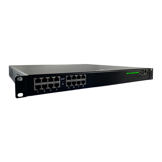
BTS500 Installation Manual 1 .2 BTS500 Rackmount Switch Overview SFP 1 ™ SFP 2 Power 1-4 Power 5-8 Battery Figure 2: BTS500 Front View – V- I- No user serviceable parts inside refer servicing to qualified service personnel Aucune pièce interne ne peut être réparer Demandez l’assistance d’un technicien qualifié... - Page 7 Installation and Operation The following are basic descriptions . Refer to the appropriate section for more detailed information . Note that the front panel may appear different based on the configuration of your system . To Use an External 50Vdc Supply SFP Ports Connect a 50V power supply to the “External DC”...
-
Page 8: Using The Fire Alarm Input For Sfi Mode
The BTS500-8R contains a Fire Alarm Input which can be typical wiring diagrams . Connections are as follows: used to activate Single-point Fire Interface mode (SFI) when used with LifeSafety Power's BX50 PoE splitters . SFI mode • I+ & I- Terminals These terminals are the input termi- allows a single FACP connection at the BTS500 to con- nals for the FAI input . -
Page 9: Section 2 - Initial Configuration
Installation and Operation Section 2 – Initial Configuration The PowerCom PoE management interface allows users to configure, monitor, and control each output port of the BTS500 series switch . PowerCom PoE is an embedded web browser based interface and does not require the installation of any dedi- cated software on the user's PC . - Page 10 BTS500 Installation Manual Figure 7: BTS500-8R Home Page...
-
Page 11: Configuring The Tcp/Ip Settings
Installation and Operation 2 .3 Configuring the TCP/IP Settings is power cycled, or rebooted . In the menu bar at the top of the browser screen, click the 2 .4 Configuring the Time Settings "Configure" link . Figure 8 shows the top section of the BTS500 The Time Settings block (See Figure 8) is where the time Configure page . - Page 12 BTS500 Installation Manual form) . Click the "Submit" button at the bottom of the "Basic" sec- v1 and v2 access . Multiple source networks can be added tion to save the settings, otherwise you will lose the settings . to the Security Name Settings block . Be sure to click the These settings will take effect after a reboot of the BTS500 .
-
Page 13: Configuring The Email Settings
Installation and Operation "Submit" button to save the settings, which will take effect after rebooting the BTS500 . The SNMP Trap Receiver IP and Port settings should be set to the proper address for the SNMP Trap receiver . Click the "Submit"... - Page 14 BTS500 Installation Manual Figure 9: Middle Section of the BTS500 Configure page...
-
Page 15: General Settings
Installation and Operation 2 .9 General Settings After clicking Submit, the new user will be active and another blank row will appear for entering the next user There are four settings in the General Settings section (See name . figure 9): Site ID Entered by user . - Page 16 BTS500 Installation Manual Figure 10: Bottom Section of the BTS500 Configure Page...
-
Page 17: The Programming Page
Installation and Operation 2 .16 User Login Record / User Activity Record "Fill All" Button (top) - This button will take all settings from Zone 1 and copy them to all other zones . Click the Show User Login Record button to show the history of login information for the BTS500 . -
Page 18: Section 3 - Using The Bts500
BTS500 Installation Manual Section 3 – Using the BTS500 3 .1 Viewing Parameters on the BTS500 Home Page Below the top section, there are nine buttons . Their func- The Home Page is shown in Figure 12 . To access the tions are described below: Home Page, click "Home"... - Page 19 Configuration and Usage Disable all ports Channel Clicking this button will disable PoE on all output ports This column shows the channel configuration for the of the BTS500 switch . port . This configuration is auto-selected by the BTS500 based on the type of device connected . Single signature Reset Selected Ports PoE devices will appear as "Channel A&B"...
-
Page 20: The Tools Page
2 . Click the "Upgrade" button . The Upgrade window will The BTS500 has a rear-panel RS485 connector for com- appear . municating with LifeSafety Power accessory boards 3 . Click "Browse . . ." and locate the new firmware file with containing an RS485 connection, such as the generation the file extension "... - Page 21 Configuration and Usage 7 . Click "Burn" to begin burning the firmware to the BTS500's processor . This process may take up to 12 minutes - DO NOT REMOVE POWER TO THE BTS500 DURING THIS PROCESS or the BTS500 will be ren- dered nonfunctional .
-
Page 22: Appendix 1 - Software Agreement
INFORMATION . crets of LIFESAFETY POWER, and Recipient shall not disclose it to any third party Notices . Recipient shall not remove or alter any copyright, trademark except to the extent required by law . Furthermore, Recipient receives no intel- or other proprietary notice that appears on or in the Software . - Page 23 LIFESAFETY POWER for the reasonable cost of the audit, SENTIAL PURPOSE . If applicable law limits the application of the provisions of in addition to such other rights and remedies as LIFESAFETY POWER may have . this Section 5(a), LIFESAFETY POWER’s liability will be limited to the maximum LIFESAFETY POWER will not conduct an audit more than once per year .
- Page 24 LifeSafety Power’s only ob- www .lifesafetypower .com ligations are those in the LifeSafety Power Standard Terms and Conditions of Sale for this product, and in no case will Tel (888) 577-2898 LifeSafety Power or its distributors be liable for any incidental, indirect, or consequential damages arising from the info1@lifesafetypower .com...
Need help?
Do you have a question about the Bitstream BTS500-8R and is the answer not in the manual?
Questions and answers