
Related Manuals for Hewland TMT-200

Summary of Contents for Hewland TMT-200
- Page 1 GEARBOX MANUAL TMT-200 Hewland Engineering Ltd +44 (0) 1628 827600 Issue: 20 Waltham Road, White Waltham info@hewland.com Date: 16/10/2020 Maidenhead, Berkshire, SL6 3LR, UK www.hewland.com...
-
Page 2: Limitation Of Liability And Warning
Hewland products are intended for use in or as high speed and high performance racing vehicles. The racing of high speed and high performance vehicles can be a very hazardous activity and therefore involves a high risk of personal injury or even death. Hewland products will not withstand all foreseeable impacts during their normal intended use in or as a racing vehicle without the likelihood of serious personal injury or death to the driver and/or passenger(s) or of damage to the Hewland products themselves which may impact the products performance and safe use. -
Page 3: Table Of Contents
Casing Parts (With Integral Gear Shift Compressor) ..........................................25 Layshaft Assembly ....................................................... 26 Pinion Shaft Assembly ....................................................27 Gear Shift Assembly (Manual Gear Shift Only) ............................................28 Gear Shift Assembly (Pneumatic Gear Shift Only) ..........................................29 ©Hewland Engineering Limited 2017... - Page 4 Barrel/Potentiometer Interfaces ................................................. 31 Temperature & Pressure Sensor Positions .............................................. 32 Part Numbering ......................................................33 Output Flange Options ....................................................41 TMT Typical Oil System Layout ................................................. 43 Running Without An Oil Cooler .................................................. 44 Revision History ......................................................45 ©Hewland Engineering Limited 2017...
-
Page 5: Figures
IGURES Figure 1-This table is taken from Hewland Standard: DOS-006-V4 ........................................6 Figure 2-This table is taken from Standard: DOS-006-V4 ............................................. 7 Figure 3- Differential Bearing Preload ................................................... 9 Figure 4-Pinion Height Setting .................................................... 10 Figure 5- Pinion Bearing Preload ..................................................11 Figure 6- Crownwheel &... -
Page 6: Technical Specification
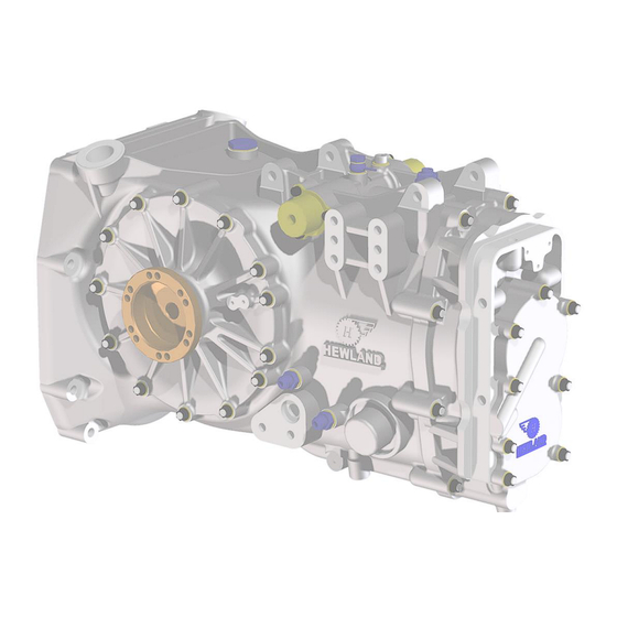
Heat treated nickel chrome steel is used to manufacture all gears and shafts. The selector forks are also steel. Lubrication is by internal pump with distribution circuit, and the oil is retained by lipped oil seals. In general configuration, the TMT-200 is a high tech racing transaxle unit which achieves the maximum effective use of power, in conjunction with extremely stiff integral rear suspension mountings. -
Page 7: Recommended Tightening Torques
Course M12.x1.5 Fine M12x1.75 Course 1/4x28 1/4x20 5/16x24 5/16x18 3/8x24 3/8x16 7/16x20 7/16x14 Figure 1-This table is taken from Hewland Standard: DOS-006-V4 Final Drive Bolts Pinion Shaft Nut Differential Centre Bolt Selector Barrel Bolt All Studs ©Hewland Engineering Limited 2017... -
Page 8: Recommended Loctite Use
Pinion / Mainshaft / Layshaft nut (ONLY IF LOCKING DEVICE IS NOT INCORPORATED INTO DESIGN) Specific fixings ✔ Crownwheel bolts / studs ✔ Selector barrel Nut ✔ Pinion bearing retaining bolts Figure 2-This table is taken from Standard: DOS-006-V4 ©Hewland Engineering Limited 2017... -
Page 9: General Notes
Thoroughly clean and inspect all parts before reassembly. Discard any worn or damaged components and replace with new ones. Use only genuine Hewland parts as replacements. These are manufactured in our workshops to the fine tolerances necessary and are rigorously inspected. -
Page 10: Differential Bearing Preload
VG-221-1 2.100” TMT-221-EW 8/35 FGC-206-2D NLT-206-2 VG-221-1 2.200” TMT-221-CW 9/35 FGC-205-2A NMT-205-2A VG-221-1 2.316” NMT-221-BW 10/31 FGC-206-2A NMT-205-2 VG-221-1C 2.316” NMT-221-AW 11/31 FGC-206-2A NMT-205-2 Refer to page 19 for part references. Figure 3- Differential Bearing Preload ©Hewland Engineering Limited 2017... -
Page 11: Pinion Height Settings
(Also etched on the head of the pinion shaft). It is also good practice to renew the pinion head bearing if the pinion shaft is being replaced. ©Hewland Engineering Limited 2017... -
Page 12: Pinion Bearing Preload
Fitting a longer reverse gear spacer (71) will decrease the pinion bearing preload, whereas shortening the Figure 5- Pinion Bearing Preload reverse gear spacer (71) will increase the pinion bearing preload. ©Hewland Engineering Limited 2017... -
Page 13: Crownwheel & Pinion Backlash Setting
However, before fitting the actual differential bearings, it is important to compare their width with that of the dummy bearings and compensate the shim Figure 6- Crownwheel & Pinion Backlash Setting thicknesses for any difference. ©Hewland Engineering Limited 2017... -
Page 14: Sequential Barrel Setting
Removal and replacement of the barrel bolt (118) is made easier if a suitable tool is located into the radial hole in the barrel (117) and the reverse blocker hole in the maincase above NB. It is not possible (or necessary) to individually adjust each fork. Figure 7- Sequential Barrel Setting ©Hewland Engineering Limited 2017... -
Page 15: Differentials
IFFERENTIALS ©Hewland Engineering Limited 2017... -
Page 16: Powerflow Differential
4) The final adjustment is simply to re-order the plate stack so as to change the number of relatively rotating faces. The diagram shows the stack setup with the maximum 12 working faces. Standard stack may be shuffled to give as few as 2 working faces. Figure 8- Powerflow Differential ©Hewland Engineering Limited 2017... -
Page 17: Differential Settings
This table is intended as a quick reference guide to percentage lock various setting permutations. 30 degree ramps with 12 working plate surfaces has been set as the 100% benchmark. Percentage Rating Ramp Angle No. of Friction Surfaces Figure 9- Differential Settings ©Hewland Engineering Limited 2017... -
Page 18: Tpt Differential Assembly
Various Bellville springs (311) and Carriers (310) are available. The first preload value given is the initial value that will be given without any additional shims. Shims can be added to the carrier to give higher preloads if required. Figure 10- TPT Differential Assembly ©Hewland Engineering Limited 2017... -
Page 19: Gearbox Assembly - (Manual Gear Shift)
Fit the bearing (28) onto the clutchshaft (18) and secure using circlip (26). Fit oilseal (44) into slave adaptor (116), and slide the slave adaptor over the clutchshaft to enable fitting of bearing circlip (27). Offer up clutchshaft assembly to the maincase with o-ring (29) in place and secure with screws (90). ©Hewland Engineering Limited 2017... - Page 20 Assemble the neutral/reverse blocker and fit it into the maincase above the barrel. NB When installing the gearbox into the car, the blocker release cable length should be adjusted so that the blocker plunger is held just clear of the barrel when a forward gear is selected. Refer to page 19 for part references. ©Hewland Engineering Limited 2017...
-
Page 21: Gearbox Assembly - (Pneumatic Gear Shift)
The 5mm set screw must be re-fitted using a suitable thread sealant to ensure the gearbox oil does not leak up through the rack. ©Hewland Engineering Limited 2017... -
Page 22: Changing Gear Ratios
Also examine the selector forks for heavy or uneven wear. Reassembly is the reverse of disassembly. Take care, when refitting the gear cluster into the maincase, to ensure location of the layshaft into its bearing Refer to page 19 for part references. ©Hewland Engineering Limited 2017... -
Page 23: Illustrated Parts List
LLUSTRATED ARTS ©Hewland Engineering Limited 2017... -
Page 24: Output Assembly
UTPUT SSEMBLY Figure 11- Output Assembly ©Hewland Engineering Limited 2017... -
Page 25: Casing Parts (Without Integral Gear Shift Compressor)
029, part number 48 is SK-2363 Gearboxes marked up to and including 029, part number 48 is SK-2363 Gearboxes marked up to and Figure 12- Casing Parts Without Integral Gear Shift Compressor including 029, part number 48 is SK-2363 ©Hewland Engineering Limited 2017... -
Page 26: Casing Parts (With Integral Gear Shift Compressor)
ALL OTHER PARTS ARE IDENTICAL TO THOSE USED IN THE CASING PARTS SHOWN IN FIGURE 12. Figure 13- Casing Parts With Integral Gear Shift Compressor ALL OTHER PARTS ARE IDENTICAL TO THOSE USED IN THE CASING PARTS SHOWN IN FIGURE 12. ©Hewland Engineering Limited 2017... -
Page 27: Layshaft Assembly
AYSHAFT SSEMBLY Figure 14- Layshaft Assembly ©Hewland Engineering Limited 2017... -
Page 28: Pinion Shaft Assembly
SHAFT HAS BEEN REPLACED IT IS ESSENTIAL TO ALWAYS RE-FORK SET THE GEARBOX IF THE PINION SHAFT HAS BEEN REPLACED Figure 15- Pinion Shaft Assembly IT IS ESSENTIAL TO ALWAYS RE-FORK ©Hewland Engineering Limited 2017 SET THE GEARBOX IF THE PINION... -
Page 29: Gear Shift Assembly (Manual Gear Shift Only)
ITEM 118 BARREL BOLT MUST BE LOCTITED AND TIGHTENED TO THE TORQUE SPECIFIED ON PAGE 5 Neutral blocking plunger parts as Figure 16- Gear Shift Assembly (Manual Gear Shift) standard manual IMPORTANT NOTE:- shift ©Hewland Engineering Limited 2017... -
Page 30: Gear Shift Assembly (Pneumatic Gear Shift Only)
ALL OTHER GEAR SHIFT PARTS ARE Figure 17- Gear Shift Assembly (Pneumatic Gear Shift) Blanking plug (224) replaces IDENTICAL TO THOSE USED IN THE neutral blocker parts (Page 25; ©Hewland Engineering Limited 2017 MANUAL GEAR SHIFT 46, 47, 74, 88 & 94) found on... -
Page 31: Input Assembly
NPUT SSEMBLY Figure 18- Input Assembly ©Hewland Engineering Limited 2017... -
Page 32: Barrel/Potentiometer Interfaces
ARREL OTENTIOMETER NTERFACES Figure 19- Barrel / Potentiometer Interfaces ©Hewland Engineering Limited 2017... -
Page 33: Temperature & Pressure Sensor Positions
& P EMPERATURE RESSURE ENSOR OSITIONS Figure 20- Temperature & Pressure Sensor Positions ©Hewland Engineering Limited 2017... -
Page 34: Part Numbering
BALL BEARING BEA-360 WEAR RING BEA-382 TAPER ROLLER OUTER CIR-082 CIRCLIP CIR-084 CIRCLIP CIR-189 CIRCLIP TMT-239-# CLUTCH SHAFT CPK-260-2 PISTON CPK-260-3 SELECTOR RACK CPK-260-5 SELECTOR RACK WASHER CST-250-C SELECTOR FORK ASSY DG-219-1A CIRCLIP DG-222-1C TAPER ROLLER BEARING ©Hewland Engineering Limited 2017... - Page 35 FGC-205-1 TAPER ROLLER BEARING FGC-205-3 BALL BEARING FGC-205-4 LIP SEAL FGC-206-1# SHIM SPACER SIDEPLATE SPACER FT-202-8 SOCKET SET SCREW FT-219-1A CIRCLIP FT-244-11 OIL SEAL FTR-202-2 BEARING RETAINING PLATE FTR-210-35 PLUNGER FTR-210-36 PLUG FTR-237-1 REVERSE IDLER SPIGOT ©Hewland Engineering Limited 2017...
- Page 36 ADAPTOR LD-201-2 STUD LD-201-5 DOWEL LIP-041 OIL SEAL NCH-266 OIL FILTER NLT-223-2 PINION HEAD BEARING SHIM NLT-222 PINION HEAD BEARING SPACER SIDEPLATE SPACER PINION SHAFT PINION SHAFT CROWNWHEEL CROWNWHEEL NMT-229 PINION SHAFT SPACER NMT-230-1 LOCKING RING ©Hewland Engineering Limited 2017...
- Page 37 SOCKET SET SCREW SCR-166 SOCKET SET SCREW (Version 1 to 16 maincases) PLU-129 SEALING SCREW (Version 17 maincases & onwards) SGT-244-13 SOCKET CAP SCREW SPH1077-M3 PAWL SPH1078-M3 PLUNGER SCR-349 ANTI-ROTATION PIN SPR-058 COMPRESSION SPRING SPR-127 COMPRESSION SPRING ©Hewland Engineering Limited 2017...
- Page 38 MAINSHAFT NUT TMT-231 REVERSE PINION GEAR TMT-234-1 OIL PUMP DRIVE TMT-239- CLUTCH SHAFT TMT-246 SELECTOR RAIL TMT-249-A REVERSE SELECTOR FORK TMT-258-1 SLAVE ADAPTOR CP3859 TMT-258-2 SLAVE ADAPTOR CP3759-3959 TMT-260-M MANUAL SELECTOR BARREL TMT-260-S SEMI-AUTO SELECTOR BARREL ©Hewland Engineering Limited 2017...
- Page 39 WSH-078 DOWTY WASHER TMT-260-5 RACK END COVER TMT-260-6 RACK SPACER TMT-260-7 RACK SEAL HOUSING FTR-260-3 RACK ORI-227 QUAD RING SPR-057 SPRING FTR-260-5 TRAVEL STOP SPACER HP-M-9008 SOCKET CAP SCREW LD-202-9 WASHER WSH-067 SHIM WASHER BEA-162 BEARING ©Hewland Engineering Limited 2017...
- Page 40 ANTI-VIBRATION MOUNTS TMT-202-1 MOUNTING PLATE SEMI-AUTO POTENTIOMETER ELC-036 TEMPERATURE SENSOR ELC-035 PRESSURE SENSOR WSH-007 DOWTY WASHER 400-222-4490-41 DOWTY WASHER BEA-263 SPLIT BEARING 400-021-4490-41 DOWTY WASHER BEA-374 BALL BEARING BEA-375 BALL BEARING CIR-021 CIRCLIP HYD-016 ADAPTOR HYD-059 ADAPTOR ©Hewland Engineering Limited 2017...
- Page 41 PNU-012 CRANK SHAFT PNU-013 PISTON PNU-019 CYLINDER HEAD LH SCR-155 SOCKET CAP SCREW SCR-317 SOCKET BUTTON HD SCREW SCR-320 ANTI ROTATION PIN TMT-308-A REAR COVER DRESSED WSH-090 DOWTY WASHER PLU-048 BLANKING PLUG SCR-209 SOCKET CAP SCREW ©Hewland Engineering Limited 2017...
-
Page 42: Output Flange Options
UTPUT LANGE PTIONS OPTIONAL RUBBER GAITOR FOR MLI-218 / MLI-218-A TRIPOD JOINTS HP-M-9054 SOCKET CAP HEAD BOLT HP-N-4030 RUBBER GAITOR ASSEMBLY Figure 21- Output Flange Options ©Hewland Engineering Limited 2017... -
Page 43: Figure 22- Transmission Tooling
Transmission Tooling Figure 22- Transmission Tooling ©Hewland Engineering Limited 2017... -
Page 44: Tmt Typical Oil System Layout
TMT T YPICAL YSTEM AYOUT Figure 23- TMT Typical Oil System Layout ©Hewland Engineering Limited 2017... -
Page 45: Running Without An Oil Cooler
UNNING ITHOUT OOLER Figure 24- Running Without An Oil Cooler ©Hewland Engineering Limited 2017... -
Page 46: Revision History
Page 04 - Weights added for Aluminium / Magnesium Casings. 24/05/2013 Page 24 - Corrected item 184 to correct number 18/10/2013 Page 01 - Hewland standard disclaimer added to front of manual. 30/06/2014 Page 05 - Recommended torque table updated. 15/07/2015 14/10/2020 Manual updated to new layout and Gear Ratio range updated, CW bolt info added to Page 9 &... - Page 47 Hewland Engineering Ltd +44 (0) 1628 827600 Waltham Road, White Waltham info@hewland.com Maidenhead, Berkshire, SL6 3LR, UK www.hewland.com...
Need help?
Do you have a question about the TMT-200 and is the answer not in the manual?
Questions and answers