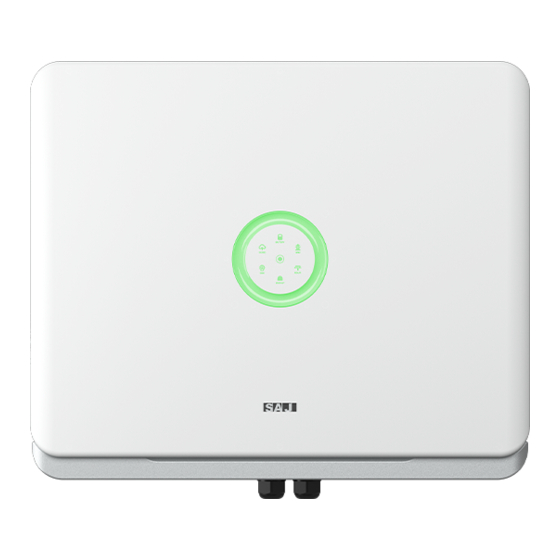
SAJ H2 Series Instruction Manual
Rooftop solar inverter
Hide thumbs
Also See for H2 Series:
- User manual (92 pages) ,
- Configuration instructions (91 pages) ,
- Manual (67 pages)
Table of Contents
Advertisement
Quick Links
Advertisement
Table of Contents

Related Manuals for SAJ H2 Series


Summary of Contents for SAJ H2 Series
- Page 1 H2-5-10K-T2...
- Page 8 MODEL H2-5K-T2 H2-6K-T2 H2-8K-T 2 H2-10K-T2 H2-5K/ 6K/ 8K/ 10K-T2 Efficiency Max. Efficiency 98.0% MODEL H2-5K-T2 H2-6K-T2 H2-8K-T2 H2-10K-T2 Euro Efficiency 97.6% PV String Input MPPT Efficiency >99.9% Max.PV Array Power [Wp]@STC 7500 9000 12000 15000 Max. Battery Charging/ Discharging Efficiency 97.6% Max.
-
Page 13: Ground Connection
Ground Connection AC Grid Wire and Backup Output Connection 2.5~6.0 Additional grounding cable cross-sectional area (mm²): 4... - Page 14 DC connector is made up of the positive connector and the negative con- nector Figure4.6 Positive and negative connectors 1. Insulated Enclosure 2. Lock Screw3. Positive/ Negative Connector ·Please place the connector separately after unpacking in order to avoid confusion for connection of cables. ·Please connect the positive connector to the positive side of the solar panels, and connect the negative connector to the negative side of the solar side.
- Page 15 2. Feed the positive and negative cables into corresponding lock screws and crimp them tightly with a wire crimper. Make sure that the withdrawal force of the pressed cable is larger than 400N. 3. Plug in the pressed positive and negative cables into relevant insulated enclosure, a “click” sound should be heard when the contact cable assembly is seated correctly.
- Page 16 3.Fix the battery cable on the battery copper terminal by positive and negative in order. 4.8.2 Note:Battery temperature can be detected by temperature sensor that integrated in the battery module, and the temperature data can be RJ45 Pin Port Definition reviewed on eSAJ App.
-
Page 17: System Connection
System Connection The system connection in Australia and New Zealand is as below, the neutral cable of AC and backup side must be connected together for the safety reason. Note: DO NOT connect the PE terminal of BACKUP side. METER Smart meter GRID... - Page 18 4.11 External AC Circuit Breaker and Residual Current Device Please install a circuit breaker to ensure the inverter is able to disconnect from grid safely. The inverter is integrated with a RCMU, however, an external RCD is needed to protect the system from tripping, either type A or type B RCD are compatible with the inverter.
- Page 20 eSAJ Home Log in to eSAJ Home, if you do not have an account, please register first. Go to the “Tool” interface and select “Remote Configuration” eSAJ APP Click on “Bluetooth” and activate the Bluetooth function on your phone, then click on “Next” Connection Choose your inverter according to your inverter SN’s tail numbers Click on the inverter to enter inverter setting...
-
Page 21: Working Modes
HYBRID SOLAR INVERTER INSTRUCTION MANUAL Export Limit Setting Working Modes 5.4.1 Selecting working modes procedures Figure 5.2 Export limit wiring schematic B2 Lithium Battery Enter the main page of local connection and click on Export limitation setting, enter the password “201561”. 5.5.1 5.4.2 Self-consumption Mode: When the solar is sufficient, electricity generated by photovoltaic... - Page 22 40 minutes. After the self-test is completed, you can save the test report. If self-test (For Italy) is failed, please contact with SAJ or your inverter supplier. grid. During the self-testing time, inverter will check the reaction time for over frequency, under frequency, overvoltage and undervoltage.
-
Page 23: Setting Reactive Power Control
HYBRID SOLAR INVERTER INSTRUCTION MANUAL Setting Reactive Power Control (For Australia) 5.7.1 Setup Fixed Power The characteristic power factor curve for cosφ (P) (Power response) mode varies the displace- Factor mode ment power factor of the output of the inverter in response to changes in the output power of Figure 5.4 the inverter. - Page 24 Master Relay Error Master Fan1 Error Master EEPROM Error Master Fan2 Error Master Temperature High Error Master Fan3 Error Master Temperature Low Error Master Fan4 Error Master Lost Communication M<->S Lost Communication between DSP and PowerMeter Master GFCI Device Error Lost Communication between M<->S Master DCI Device Error load PowerMeter"...
-
Page 25: Contact Saj
Guangzhou Sanjing Electric Co., Ltd. SAJ Innovation Park, No.9, Lizhishan Road, Guangzhou Science City, Guangdong, P.R.China. Postcode: 510663 Contact SAJ Web: http: //www.saj-electric.com Technical Support & Service Tel: +86 20 6660 8588 Fax: +86 206660 8589 E-mail: service@saj-electric.com International Sales...
Need help?
Do you have a question about the H2 Series and is the answer not in the manual?
Questions and answers