
Related Manuals for USR IOT USR-M100


Summary of Contents for USR IOT USR-M100
- Page 1 USR-DR404 AT 指令集 USR-M100 Industrial Edge I/O Gateway Modular Remote Terminal Unit(RTU) User Manual V1.0.0 Build a Smarter IoT world, Your Trustworthy Partner...
-
Page 2: Table Of Contents
User Manual Content 1. Introduction ....................................5 1.1. Overview ..................................5 1.2. Features ...................................5 2. Get started ....................................6 2.1. Installation ..................................6 2.1.1. DIN-Rail mounting ..............................6 2.1.2. Wall mounting ................................ 7 2.2. Serial port ..................................7 2.3. I/O interfaces ...................................7 2.3.1. - Page 3 User Manual 3.2. Configuration software ..............................33 3.2.1. Discovering your gateway ............................ 33 3.2.2. Network setting ..............................33 3.2.3. Reboot the device ..............................34 3.2.4. Restore to factory default settings ........................34 3.2.5. Open web server ..............................35 4. Operation modes ..................................35 4.1.
- Page 4 User Manual 7.6. Serial Printer setting ..............................68 7.7. NTP ....................................70 7.8. SNMP .................................... 71 8. MQTT gateway ..................................72 8.1. Basic settings .................................72 8.2. Publishing a message ..............................75 8.2.1. MQTT.fx tool introduction .............................75 8.2.2. Transparent transmission .............................77 8.2.3. Topic distribution ..............................79 8.2.4.
- Page 5 User Manual 10.4. MQTT query/control ..............................114 10.4.1. DI status query ..............................116 10.4.2. AI status query ..............................117 10.4.3. DO control/query ............................. 117 10.5. DO Timing trigger control ............................118 10.6. Edging computing and linkage control ........................118 10.6.1. Add IO module ..............................119 10.6.2.
-
Page 6: Introduction
OT/IT protocol conversion. With the ability to convert between multiple protocols, USR-M100 can convert the collected I/O and serial data to protocols suitable for different upper-level software. For example, cloud service via MQTT, SCADA via Modbus TCP, web server via HTTP, and more. -
Page 7: Get Started
2. Get started Since the USR-M100 is connected through a TCP/IP network, you may need to know some basic facts about networking in order to connect the server correctly. Specifications and dimensions are not provided in this manual. Please refer to datasheet for more information. -
Page 8: Wall Mounting
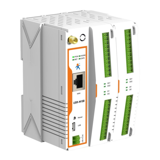
1200m regardless of boosters and repeaters. Fig. 2 USR-M100 interfaces 2.3. I/O interfaces USR-M100 is equipped with two 11-pin Terminal blocks that are used for I/O interfaces. The pin assignments of terminal block are Your Trustworthy Industrial IoT Partner www.pusr.com... - Page 9 User Manual shown in table 1. The PIN assignments are also marked on the device’s nameplate, in order to avoid confusion. Table 1 Terminal pin assignments Terminal block1 Definition Terminal block2 Definition DO1 NC Relay Output 1 normal close COM 2 RS485 A DO1 COM Relay Output 1 Common COM 2 RS485 B...
-
Page 10: I/O Specifications
User Manual 2.3.1. I/O specifications Table 2 I/O specification Inputs DI channels Input Type Dry/Wet contact Wet contact On: 9 to 36 VDC Off: 0 to 2 VDC Digital inputs Dry contact On: close Off: open Range 9-36V DC Input filter time Software configurable,10~65535ms Quantity Type... -
Page 11: Modbus Address Mapping Table
–wire range:28~16 AWG(0.2~0.1 mm ), strip length 10mm 2.3.3. Modbus address mapping table The internal register map of USR-M100 field controller node is the data map of digital input and output and analog input module. Your Trustworthy Industrial IoT Partner www.pusr.com... -
Page 12: Power Supply
2.4. Power supply The USR-M100 I/O gateway provides 2-pin power supply input terminal. The power supply support anti-reverse protection. Power supply range: 9~36VDC. 2.5. Ethernet RJ45 interface The 10Base-T/100Base-TX adaptive Ethernet RJ45 interface supports automatic MDI/MDIX connection, refer to Fig.7 below for the pin distribution of the RJ45 interface. -
Page 13: Factory Default Settings
USR-M100 has a built-in Web server, which provides a convenient way to access and configure the remote IO module. Users can use Edge , Firefox or Google browser to access it. This chapter is a quick introduction to the USR-M100 smart IO gateway. It is recommended that users read this chapter and follow the instructions once for the system, and you will have a basic understanding of the product. -
Page 14: Hardware Connection
2.8.2. Hardware connection For fast networking of USR-M100 smart RTU, you need to prepare a PC, a router, a network cable, a serial cable, and a DC12V/1A power supply. The hardware connection is shown in Fig.10. To establish a TCP / IP network all devices must be connected to the same network either locally or via gateway connections. -
Page 15: Network Configuration(Step1
User Manual Fig. 10 Hardware connection Connect the power line with the USR-M100 power input. If the power is properly supplied, the “PWR” LED will show a solid red color. After the system is ready, the “WORK” LED will blink. - Page 16 192.168.0.X (X is any valid value from 2 to 253 except 7). The specific Windows system operation page is shown in Fig.14. you can access the Web page of the USR-M100 gateway through browser as mentioned above. Your Trustworthy Industrial IoT Partner...
-
Page 17: Data Transmission Test(Step2 And 3
You can select an operation mode in socket setting page, but for now we use default parameters to test, i.e TCP server. Now USR-TCP232-Test works as TCP client, you need configure the server IP and port, that is 172.16.14.73:23 of USR-M100 gateway, the IP address of PC is 172.16.14.15. -
Page 18: Reload Factory Settings Button
Press the “ Reload ” button (inside a small hole) on the back panel for 3-15 seconds and then release or follow the procedure in Section 3.1.9 , to restore the USR-M100 gateway to the factory default settings. 2.10. Technical support and assistance Please visit the USR IoT website: https://www.pusr.com... -
Page 19: Configuration And Parameter Details
Every USR-M100 Industrial IO gateway is equipped with a built-in web server in the firmware. Therefore, the device can be accessed by using a web browser for configuring by entering the device’s IP address in the URL field of your web browser. An authentication will be required and you will have to enter the username (Default value is “admin ”) and password (Default value is “admin”) for... -
Page 20: Ip Settings
IP settings You must assign a valid IP address to the USR-M100 before it will work in your network environment. The IP address must be unique within the network. If the device is connected to the Internet and should connect to other servers over the Internet to get some Your Trustworthy Industrial IoT Partner www.pusr.com... - Page 21 User Manual services such as Network Time Protocol (NTP) server, you will need to configure the DNS server in order to be able to resolve the host name of the NTP server. The detailed description of the configuration parameters on this interface is shown in table 8. Fig.
-
Page 22: Serial Port Settings
Fig.19. Details on work mode connectivity protocols and its Chapter 4 settings of USR-M100 gateway are given in Operation modes, this section will only focus on the part of parameter description. - Page 23 The default is disable. If you want to keep connection continually, you can disable it. Data idle Time is the reconnection(TCP/UDP time period for which the device waits for data. If the USR-M100 gateway does not receive data during client) established idle time(timeout), the USR-M100 gateway will disconnect temporarily.
-
Page 24: Websocket Server
User Manual arrived. The M100 gateway determines the end of the serial acknowledgement through a response timeout. Response timeout If the Modbus device does not receive a response within the time specified here, the communication times out. Valid settings are from 10 – 9999ms. Modbus TCP exception This option is used to enable modbus exception checking. - Page 25 Select the mqtt protocol version. V3.1 and V3.1.1 are supported. Client ID The client ID defined the identifier of the USR-M100 Gateway. The IDs of the various MQTT clients have to be unique for the respective MQTT Broker. If two MQTT clients are using an identical ID, the connections of theses clients to the MQTT Broker are disconnected.
- Page 26 For example, topic name, {"message": "Hello from USR-M100 gateway"} as serial data. Different topics are allowed to have the same topic name. In this way, data is pushed to all topics with the same topic name.
-
Page 27: Edge Computing
User Manual again and again until acknowledgment is received. QoS 2: exactly once. The MQTT protocol uses the confirmation of confirmations to ensure that a message is delivered exactly once. Retained message By setting the Retain flag the MQTT Broker is instructed to save the most recent data value for the topic. - Page 28 User Manual Fig. 25 Edge computing enabled Fig. 26 Modbus slaves and datapoints configuration Table 14 Modbus RTU poll configuration Parameter Item Description Device name The Modbus slave device identifier, which is unique for the current gateway. The device name must be less than 30 characters in length, and can contain letters, digits, underscores (_).
- Page 29 User Manual If 60 milliseconds is required to collect the data of each property, the total time required to collect the data of all properties is calculated as follows: Total required time = Time required to collect the data of each property (60 ms) × Number of properties for the slave device.
-
Page 30: Io Settings
IO settings USR-M100 gateway can support a number of Digital Input (DI), Digital Output (DO-Relays ), Analog Input (AI) ports. There are a few combinations of I/O extension board in develop. Because the I/O status of M100 is mainly displayed via Modbus protocol, the user has Your Trustworthy Industrial IoT Partner www.pusr.com... - Page 31 User Manual to configure the Modbus settings if the user wants to use the Modbus protocol. Fig.29 shows the parameter that must be set for the Modbus protocol that is the Modbus Slave ID. Fig. 28 IO control Fig. 29 IO function Table 17 IO function...
-
Page 32: Cloud Service
The password of web console and can be modified. up to 16 characters,can’t be NULL UART cache Click the option to enable serial buffer. By default, USR-M100 will empty its serial buffer when a new TCP connection is established. This means that the TCP application will not receive buffered serial data during a TCP link breakage. -
Page 33: Management
C. Firmware upgrade USR IoT continually upgrades its firmware to add new features and optimize performance. Please contact the sales to obtain the latest version of the firmware. Before upgrading the firmware, please make sure that the device has a reliable power source that will not be powered off or restarted during the firmware upgrading process(please be patient as this whole process might take up to 1 -2 minutes). -
Page 34: Configuration Software
3.2.2. Network setting Sometime the USR-M100 gateway might not be in the same subnet as your PC, therefore, you will have to use this utility to locate it in your environment. To configure each device, first click to select the desired device (default IP:192.168.0.7) in the list of configuration utility, and then change the IP address to avoid any IP address conflict with other hosts on your LAN, save your change. -
Page 35: Reboot The Device
User Manual Fig. 33 Changing network settings 3.2.3. Reboot the device This function is available to allow you to reset the gateway. The function disconnects both the ethernet and serial connections. The function also allows the gateway to save new configuration settings to flash memory. To reset the device: 1. -
Page 36: Open Web Server
Properties In TCP server mode, the TCP connection is initiated from the host to the USR-M100 gateway. This operation mode supports a maximum of 16 simultaneous connections for each serial port on the gateway from a single or multiple hosts. After the connection is established between the gateway and the remote host computer (remote TCP client) , data can be transmitted in both directions. - Page 37 Fig.36 shows an example of test in this mode. By selecting the TCP Server work mode, a TCP client program on a remote host computer should be prepared to connect to USR-M100. Server IP is IP address of USR-M100, server port is local port of USR-M100. In this case, IP address of USR-M100 is 172.16.14.73.
-
Page 38: Multihost Setting
The local port number can be ignored and no configuration is required. USR-M100 supports SSL (TLS v1.0 or v1.2) data encryption in this operating mode. - Page 39 User Manual Fig. 38 TCP client work mode Please follow the following steps to configure connection settings of the work mode for Uart1 port. Click on the “Uart1” tab on the menu frame on the left side of Web UI to go to Uart1 page as shown in Fig.38. 2.
-
Page 40: Ssl/Tls
User Manual Fig. 39 M100 initiating TCP connection 4.2.2. SSL/TLS If SSL certificate authentication is enabled on the remote server, user need to configure SSL encryption parameters on M100. User can select TLS1.0 or TLS1.2 version protocol. User can select None certificate Authentication, server certificate authentication and bidirectional certificate authentication. -
Page 41: Udp Server
When the working mode of the device is UDP server, the remote device must also work in UDP mode. You only need to specify the Local Port that USR-M100 should listen to. In UDP server mode, serial port data is always sent to the last peer UDP device(IP and port) that communicates with the USR-M100, and the USR-M100 can record the IP and port number only after the peer UDP device sends data to the USR-M100 first. -
Page 42: Udp Client
User Manual updates the destination IP address and port number, and sends the data back to the latest IP address and port number. In this case, IP address of USR-M100 is 172.16.14.73, host IP address is 172.16.14.15. Fig. 43 UDP transmission test 4.4. -
Page 43: Udp Multicast
All configurations take effect after a system reboot. Fig.45 shows an example of test in this mode. In this case, IP address of USR-M100 is 172.16.14.73, host IP address is 172.16.14.15. Fig. 45 UDP client test 4.4.2. - Page 44 User Manual Fig. 46 USR-M100 #1 UDP multicast setting Fig. 47 USR-M100 #2 UDP multicast setting Fig.48 shows an example of test in this mode with two M100s. Your Trustworthy Industrial IoT Partner www.pusr.com...
-
Page 45: Http Client
User Manual Fig. 48 UDP multicast transmission test 4.5. HTTP Client 4.5.1. Properties When the operation mode of this device is Httpd Client, users need to specify the remote httpd server's address, port, method and other parameters. The device will submit the serially received data to the httpd server in the form of GET or POST. At the same time, the data sent by the httpd server can be transparently transmitted to the serial port. -
Page 46: Https
User Manual 5. Fill in the HTTPD request header as needed. 6. Fill in the HTTPD address, that is, the address of the HTTP server, which can be an IP address or a domain name (the ability to connect to foreign countries is required). 7. - Page 47 User Manual Fig. 51 Websocket server setting 5. Click on the websocket to serial tab,browser will connect to the websocket server of M100 automatically. Fig. 52 Browser as websocket client to connect M100 Fig.53 shows an example of test in this mode. Your Trustworthy Industrial IoT Partner www.pusr.com...
-
Page 48: Virtual Com Port
Virtual COM ports on host computer allows remote access of serial devices over TCP/IP network that works like local native COM ports. Since USR-M100 gateway enable network operation of instruments equipped with an RS-232/485 communication port, your SCADA and data collection system will be able to access all instruments connected to a standard TCP/IP network, regardless of whether the instruments are used locally or at a remote site. - Page 49 User Manual Fig. 54 Install wizard 1 Fig. 55 Install wizard 2 Once the installation of the package is finished a start screen displays. Click start to conclude the process and launch the VCOM software. Your Trustworthy Industrial IoT Partner www.pusr.com...
-
Page 50: Tcp Server Application With Virtual Com
TCP client connecting to the gateway. The characteristic of this mode is that the IP address of the host can be changed (usually automatically assigned by the router), and the IP address of the gateway must be fixed. Fig. 57 TCP server mode in USR-M100 Your Trustworthy Industrial IoT Partner www.pusr.com... - Page 51 3. After selecting the virtual COM ports, please enter the IP Address of the gateway with the specified Port Number. The Port Number here is the Local Listening Port for the gateway which is specified in the Local Port field of Fig.60. In this case, IP address of USR-M100 is 172.16.14.12. Your Trustworthy Industrial IoT Partner...
-
Page 52: Tcp Client Application With Virtual Com
User Manual Fig. 60 Virtual COM port mapping 4. Click new to add the Virtual COM11. Click client COM11 on the left side of VCOM panel to check the status. If status become connected, the process is completed. Fig. 61 Virtual COM11 status 5.2. - Page 53 User Manual Fig. 62 TCP client mode in USR-M100 Fig. 63 New Virtual COM connection 2. Select one COM port as the Virtual COM port before proceeding as shown in Fig.64. Note that if a COM port number is used by other application or your operating system, you can not select it.
-
Page 54: Enable Rfc2217 Through Virtual Com
This function is only allowed when the working mode is TCP Server and TCP Client. Note that this protocol is used to change the serial port parameters of USR-M100. In this case, IP address of USR-M100 is 172.16.14.34. - Page 55 User Manual Fig. 66 RFC2217 enabled Fig. 67 enable RFC2217 in VCOM When we change serial parameters in Virtual COM port 1, we can see these parameters have took effect in serial port of USR-M100. Your Trustworthy Industrial IoT Partner www.pusr.com...
-
Page 56: Pusr Customized Rfc2217 Protocol
User Manual Fig. 68 Synchronizing serial port parameters 5.3.1. PUSR customized RFC2217 protocol Table 19 Com Port Control commands Name Header Baud rate Serial parameter definition Sum check Length(bytes) Big endian, Data bits/stop bits/parity Check sum of 4 bytes of e.g. -
Page 57: Modbus Tcp/Rtu Gateway
The device supports multiple hosts to query data from the slave in Q&A mode. Please select modbus polling function as shown in Fig.70. When USR-M100 gateway does not receive a response from the serial port after a response timeout, the device replies with an acknowledgement and then processes the next host request. -
Page 58: Serial Master With Ethernet Slave
Modbus TCP master settings Open the Modbus Poll and Modbus Slave software, go to "Connect" -> "Connect", and the connection parameters are configured as follows, in this case, IP address of USR-M100 is 172.16.14.12. Fig. 71 Modbus emulator settings(Ethernet master and serial slave) 6.2. - Page 59 Modbus TCP slave settings Open the Modbus Poll and Modbus Slave software, go to "Connect" -> "Connect", and the connection parameters are configured as follows, in this case, IP address of USR-M100 is 172.16.14.12, host IP address is 172.16.14.15. Fig. 74...
-
Page 60: Serial Master With Serial Slaves
User Manual 6.3. Serial master with serial slaves When the HMI is Modbus RTU Master, all M100 must enable or disable ModbusTCP function at the same time, the remote device must work in Modbus RTU Slave mode. The M100 supports up to 16 simultaneous TCP connections. Fig. -
Page 61: Serial Master Via Virtual Com With Serial Slaves
User Manual Fig. 77 Modbus RTU slave settings Fig. 78 Modbus emulator settings(serial master and serial slave) 6.4. Serial master via virtual COM with serial slaves When the host computer is Modbus RTU master, if we use VCOM, the Modbus TCP function must be disabled, the remote device must work in Modbus RTU Slave mode. - Page 62 User Manual Fig. 79 New virtual COM port mapping Fig. 80 Mapping a virtual COM port Your Trustworthy Industrial IoT Partner www.pusr.com...
- Page 63 User Manual Fig. 81 Virtual COM port mapping details Fig. 82 Serial device settings Your Trustworthy Industrial IoT Partner www.pusr.com...
-
Page 64: Modbus Poll With Serial Heartbeat Packet
User Manual Fig. 83 Modbus emulator settings(serial master and serial slave) 6.5. Modbus poll with serial heartbeat packet When the M100 is Modbus RTU Master, the serial device work in Modbus RTU Slave mode, the ModbusTCP function must be disabled. M100 works in TCP server mode, it supports up to 16 TCP connections. -
Page 65: Advanced Features
Data packing mechanism Packet time: USR-M100 will transmit the serial data in its buffer when the specified time interval has reached and no more serial data comes in. The default value is calculated automatically based on the baud rate. If the automatic value results in chopped data, the timeout could be increased manually by specifying a larger value in the text box above. -
Page 66: Heartbeat Packet
Packet length: USR-M100 will transmit the serial data in its buffer when the specified length in the unit of bytes has reached. If you would like USR-M100 to queue the data until it reaches a specific length,the data length can be configured for 1 to 1460 bytes. If the data length (in bytes) matches the configured value, the data will be forced out. -
Page 67: Registration Packet
User Manual Fig. 89 Network heartbeat packets 7.3. Registration packet This function is only allowed when the working mode is UDP and TCP Client. The content of the registration packet can be up to 40 bytes long. Users can choose to display this content in hexadecimal format or ASCII format. Once connected: The registration packet is only sent once when the network connection is established;... -
Page 68: Socket B
User Manual Fig. 91 Registration packet method 7.4. Socket B Socket B supports TCP Client and UDP Client. Socket B and Socket A share the registration packet and heartbeat packet. When Socket B initiates a connection, it uses a random local port number to connect to the target server. Fig. -
Page 69: Serial Printer Setting
Serial Printer setting USR-M100 gateways transform any serial device into an Ethernet-capable device that can be used in a network. These gateways allow serial devices such as a printer, control mechanisms or control systems to be used in a network without relying on the serial port of a computer for connectivity. - Page 70 User Manual Fig. 95 Serial printer setting wizard 1 Fig. 96 Serial printer setting wizard 1 Your Trustworthy Industrial IoT Partner www.pusr.com...
-
Page 71: Ntp
User Manual Fig. 97 Serial printer setting wizard 1 Fig. 98 Serial printer setting wizard 1 7.7. If M100 is connected to the internet or to a local NTP server, the Date/time can be set automatically by enable NTP function. If this option is chosen, the default value “cn.ntp.org.cn”... -
Page 72: Snmp
User Manual configure the DNS server in order to be able to resolve the host name of the NTP server. Fig. 99 NTP settings 7.8. SNMP The Simple Network Management Protocol (SNMP) is used by network management software to monitor devices in a network, to retrieve network status information of the devices, and to configure network parameters of the devices. -
Page 73: Mqtt Gateway
User Manual Firmware version .1.3.6.1.2.1.12.1.0 Hardware version .1.3.6.1.2.1.12.2.0 RAM usage .1.3.6.1.2.1.12.3.0 CPU usage .1.3.6.1.2.1.12.4.0 Preferred DNS .1.3.6.1.2.1.12.5.0 Alternate DNS .1.3.6.1.2.1.12.6.0 Fig. 101 SNMP test 8. MQTT gateway Although the MQTT protocol has been around for nearly three decades, the design of the protocol makes it ideal for IIoT (Industrial Internet of Things) applications, the latest trend in automation engineering. - Page 74 User Manual Fig. 102 MQTT broker setting If your broker has enabled user authentication, you can fill in the information of Username and Password in the configuration item. Fig. 103 User credential When you need to enable SSL/TLS authentication, you need to set the SSL/TLS configuration item. The two versions,TLS 1.0 and TLS 1.2 are provided.
- Page 75 User Manual Fig. 104 SSL/TLS connection You can configure the Will Message. The values of Last-Will-QoS and Last-Will-Retain are filled with 0 and False by default. When you enter the values of Last-Will-Topic and Last-Will-Payload, you can complete the configuration of Will Message. Fig.
-
Page 76: Publishing A Message
User Manual Fig. 106 EMQX broker connection To view the status of the device, choose Status>Overview, the device is in the CONNECTED state, the connection to IoT Hub is successful, and publishing and subscribing operations can be performed. Fig. 107 MQTT connection status 8.2. - Page 77 User Manual Fig. 108 MQTT.fx main page First, the MQTT client and Broker need to establish a connection to communicate. Click the configuration icon on the right side of the input box in the connection address bar to enter the specific connection configuration. Select the Profile Type as MQTT Broker. Fill in broker.emqx.io for Broker Address and 1883 for Broker Port, as shown in the figure below: Fig.
-
Page 78: Transparent Transmission
User Manual Fig. 110 Successful connection 8.2.2. Transparent transmission In the Publish field, select Publish topic1, enter the topic, bind to the Port1, select Qos 0, uncheck retained message. We use the /PubTopic1 as an example to describe the process. After finishing configuring the Publish topic1, please scroll down to the bottom of the page and click on "Save &... - Page 79 User Manual Fig. 112 Subscribe to the M100 topic Launch serial debug assistant on PC, and open COM Port with the M100’s serial default settings as below: Fig. 113 Serial debug assistant setting Click send button. On the MQTT.fx page, you will receive a message from the cloud that was sent from the M100. For Payload decoded by select “JSON Pretty Format Decoder”...
-
Page 80: Topic Distribution
User Manual Fig. 114 Receive message from M100 8.2.3. Topic distribution In the Publish field, select Publish topic2, enter the topic, topic alias, bind to the Port1, select Qos 0, uncheck retained message. We use the /PubTopic2 as an example to describe the process. After finishing configuring the Publish topic2, please scroll down to the bottom of the page and click on "Save &... - Page 81 User Manual Fig. 116 Subscribe to the M100 topic Launch serial debug assistant on PC, and open COM Port with the M100’s serial default settings as below: Fig. 117 Serial debug assistant setting Enter the correct serial data format: topic alias,payload-test,{"message":"hello from M100"}, Click send button. On the MQTT.fx page, you will receive a message from the cloud that was sent from the M100.
-
Page 82: Custom Mode
User Manual Fig. 118 Receive message from M100 8.2.4. Custom mode In the Publish field, select Custom mode, bind to the Port1. Click on "Save & Apply" button to save all the changes that you have made. All configurations take effect after a system reboot. Fig. - Page 83 User Manual Fig. 120 Subscribe to the M100 topic Launch serial debug assistant on PC, and open COM Port with the M100’s serial default settings as below: Fig. 121 Serial debug assistant setting Enter the correct serial data format: topic,Qos,Retain,payload-/PubTopic3,0,ON,{"message":"hello from M100"}, Click send button. On the MQTT.fx page, you will receive a message from the cloud that was sent from the M100.
-
Page 84: Subscribe To A Topic
User Manual Fig. 122 Receive message from M100 8.3. Subscribe to a topic In the Subscribe field, select Subscribe topic1, enter the topic, bind to the Port1, select Qos 0. We use the /SubTopic1 as an example to describe the process. After finishing configuring the Subscribe topic1, please scroll down to the bottom of the page and click on "Save &... - Page 85 User Manual Fig. 124 Publish message to M100 Click Publish to send the messages and return to the serial debug assistant. We can find that the serial port has received the message, as shown in the following figure: Fig. 125 Receive message from cloud Your Trustworthy Industrial IoT Partner www.pusr.com...
-
Page 86: Edge Computing
9.1. Add modbus slave device Connect serial device to the serial port of USR-M100 gateway, and then configure the slave parameter on the data acquisition tab. Click add slave to add a device, click edit to configure the device. Fig. 127... -
Page 87: Add Modbus Data Points
User Manual Fig. 128 Polling slave device configuration In the slave property, enter the device name, bind to the Port1, enter the slave address and polling interval, enable merge collection function, the description of the configuration parameters on this interface is shown in table 14. -
Page 88: Data Points Configuration
User Manual Table 23 Data types Type Function code Objects count Note Bool Bool int8 Integer 8 bit uint8 Unsigned integer 8 bit int16 Integer 16 bit. Big-endian.high byte first uint16 Unsigned integer 16 bit. Big-endian. int32(ABCD) Integer 32 bit. Big-endian. int32(CDAB) Integer 32 bit. - Page 89 User Manual Fig. 130 Data point configuration In the data point property, enter the node name, select modbus function code, enter the register address and response timeout, select the right data type, input the calculation formula, the description of the configuration parameters on this interface is shown in table 15.
-
Page 90: Export And Import Configuration
User Manual Fig. 132 Modbus polling command 9.3. Export and import configuration There are three main reasons for using the Import and Export functions. Applying the same configuration to multiple units. The Import/Export configuration function is a convenient way to apply the ... - Page 91 User Manual Fig. 133 Export the configuration file Fig. 134 Configuration file Once the file is saved, it can be imported into your target unit to duplicate the same settings. Select the target unit first and click the choose file button to import. Select the file you want to import, and then click the open button. The data points setting will display on the webpage.
-
Page 92: Data Report
User Manual Fig. 135 Import the configuration file 9.4. Data report 9.4.1. Communication channel Users can select TCP/UDP/HTTP in socketA of each serial port, MQTT Gateway, or AWS IOT service as the communication channel. When select MQTT or AWS IOT channel, user need configure the MQTT broker parameters in MQTT Gateway tab or Cloud service tab at first, and setting the report topic in the Fig.137. -
Page 93: Report Method
User Manual Fig. 137 MQTT data report setting 9.4.2. Report method There are three ways to report the data acquired to the communication channel: on change, interval, timer. The description of the table 16 configuration parameters on this interface is shown in . -
Page 94: Payload-Json Template
User Manual Fig. 139 Interval and timer report 9.4.3. Payload-Json template A JSON object contains zero, one, or more key-value pairs, also called properties. The object is surrounded by curly braces {}. Every key-value pair is separated by a comma. The order of the key-value pair is irrelevant. A JSON array contains zero, one, or more ordered elements, separated by a comma. - Page 95 User Manual "sensor2": { "temperature": "temperature2", "humidity": "humidity2", "user_define": "living room" "event_time": "sys_net_time" "device_id":"sys_mac" We can use a tool to compact it. Below is a free online tool: https://jsonformatter.org/. Paste the message in the column on the left and then, click Minify JSON. It will show a compact JSON format message in the column on the right. Click Copy to Clipboard. Fig.
-
Page 96: Test
We now use modbus slave software to simulate two modbus slave device. The connection and and parameters settings are show in Fig.142. USB to RS485 converters are connecting PC with serial UART1 of USR-M100 gateway. We use MQTT.fx to connect to the same broker and subscribe the report topic of USR-M100, we can see the message transmitted at the specified interval. - Page 97 User Manual Fig. 143 Modbus slave simulation Fig. 144 Data acquisition setting Your Trustworthy Industrial IoT Partner www.pusr.com...
-
Page 98: Data Query
User Manual Fig. 145 Data report setting Fig. 146 Message reported 9.5. Data query There are three methods to actively query the data collected through the serial port from the communication channel: Json format, Modbus TCP, Modbus RTU. Firstly, user need enable the data query function. We can query data by Json format in MQTT or HTTP channel,and via modbus TCP or RTU format in TCP/UDP mode. - Page 99 User Manual Fig. 147 JSON query type The Json content need conform to template described in section 9.4.3. Fig. 148 Json query message Your Trustworthy Industrial IoT Partner www.pusr.com...
-
Page 100: Modbus Slave Address And Register Mapping
User Manual Fig. 149 Json response message 9.5.2. Modbus slave address and register mapping This function is very useful in data query and only used in modbus TCP/RTU query mode. When user select Modbus TCP/RTU query mode to get data, the M100 gateway will be confused if there are the same slave address in different serial port or same register address in different slave devices. -
Page 101: Modbus Tcp
User Manual Fig. 151 Slave address mapping Fig. 152 Register address mapping 9.5.3. Modbus TCP When select socket channel, user need configure parameters of the socket A of Uart1 in PORT tab at first, then select Modbus TCP query type. We use slave address mapping and register mapping described in section 9.5.2 as here for illustration. Your Trustworthy Industrial IoT Partner www.pusr.com... - Page 102 User Manual Fig. 153 Modbus TCP query type Fig. 154 Socket A parameters setting Your Trustworthy Industrial IoT Partner www.pusr.com...
-
Page 103: Modbus Rtu
User Manual Fig. 155 Modbus TCP simulator settings Fig. 156 Modbus TCP response 9.5.4. Modbus RTU When select socket channel, user need configure parameters of the socket A of Uart1 in PORT tab at first, then select Modbus RTU query type. We use slave address mapping here for illustration. Your Trustworthy Industrial IoT Partner www.pusr.com... - Page 104 User Manual Fig. 157 Modbus RTU query type Fig. 158 Modbus RTU simulator settings Your Trustworthy Industrial IoT Partner www.pusr.com...
- Page 105 User Manual Fig. 159 Modbus RTU response Your Trustworthy Industrial IoT Partner www.pusr.com...
-
Page 106: Io Channels
10. IO channels USR-M100 can support a number of Digital Input (DI), Relays (Rly), Analog Input (AI) ports. All modules are equipped with an in-built web server, which allows for showing the module status and changing the configuration. To access the web server, open the browser and enter the IP address of the module, default address for a new module (default IP address is 192.168.0.7). -
Page 107: Modbus Tcp Query/Control
User Manual Fig. 161 IO configuration 10.2. Modbus TCP query/control We choose socket A of Uart1 as the communication channel as an example to illustrate it. User can also choose socket B and other Uart port. Fig. 162 Socket setting for modbus TCP Your Trustworthy Industrial IoT Partner www.pusr.com... -
Page 108: Di Status Query
User Manual Fig. 163 Modbus TCP simulator settings 10.2.1. DI status query Fig. 164 Slave ID and register address Your Trustworthy Industrial IoT Partner www.pusr.com... - Page 109 User Manual Fig. 165 Read DI values Fig. 166 DI values Your Trustworthy Industrial IoT Partner www.pusr.com...
-
Page 110: Ai Status Query
User Manual 10.2.2. AI status query Fig. 167 Slave ID and register address Fig. 168 Read AI values Your Trustworthy Industrial IoT Partner www.pusr.com... -
Page 111: Do Query/Control
User Manual 10.2.3. DO query/control Fig. 169 Slave ID and register address Fig. 170 Read DO status Your Trustworthy Industrial IoT Partner www.pusr.com... -
Page 112: Modbus Rtu Query/Control
User Manual Fig. 171 Write DO Fig. 172 DO Values 10.3. Modbus RTU query/control We choose socket A of Uart1 as the communication channel as an example to illustrate it. User can also choose socket B and other Uart port. Your Trustworthy Industrial IoT Partner www.pusr.com... -
Page 113: Di Status Query
User Manual Fig. 173 Modbus RTU simulator settings 10.3.1. DI status query Fig. 174 Read DI values Your Trustworthy Industrial IoT Partner www.pusr.com... -
Page 114: Ai Status Query
User Manual 10.3.2. AI status query Fig. 175 Read AI values 10.3.3. DO control/query Fig. 176 Read DO status Your Trustworthy Industrial IoT Partner www.pusr.com... -
Page 115: Mqtt Query/Control
User Manual Fig. 177 Write DO Fig. 178 DO Values 10.4. MQTT query/control When enable MQTT gateway or AWS IOT service, user need configure the MQTT broker parameters in MQTT Gateway tab or Cloud service tab at first. Users can query or control IO ports by enabling IO control/query box on publish or subscribe tab. Note that the query or response data is modbus RTU protocol. - Page 116 User Manual Fig. 179 MQTT gateway settings Fig. 180 Publish topic IO control/query Your Trustworthy Industrial IoT Partner www.pusr.com...
-
Page 117: Di Status Query
User Manual Fig. 181 Subscribe topic IO control/query 10.4.1. DI status query Fig. 182 DI query and response Your Trustworthy Industrial IoT Partner www.pusr.com... -
Page 118: Ai Status Query
User Manual 10.4.2. AI status query Fig. 183 AI query and response 10.4.3. DO control/query Fig. 184 DO query and response Your Trustworthy Industrial IoT Partner www.pusr.com... -
Page 119: Do Timing Trigger Control
User Manual Fig. 185 DO control and response 10.5. DO Timing trigger control USR-M100 support 6 timing tasks, users can do scheduled action for DO or device restart. Fig. 186 Timing trigger control 10.6. Edging computing and linkage control First,users need to enable edge computing function. -
Page 120: Add Io Module
User Manual 10.6.1. Add IO module Click add slave to add the IO port. In the slave property, enter the device name, bind to the IO, enter the polling interval. Click save. Fig. 187 Add IO Port 10.6.2. Add IO data points Click add nodes to add the IO data points. -
Page 121: Io Status Report
User Manual Fig. 189 Save the configuration After finishing configuring the slave device, please scroll down to the bottom of the page and click on "Save" button to save all the changes that you have made. All configurations take effect after a system reboot. 10.6.3. -
Page 122: Io Query
User Manual Fig. 191 IO status report test 10.6.4. IO query Here we use MQTT as an example. Fig. 192 IO status query Your Trustworthy Industrial IoT Partner www.pusr.com... -
Page 123: Linkage Control
User Manual Fig. 193 IO status query test 10.6.5. Linkage control When enable Edge computing function, users can set trigger conditions for Digital output control. There are two control logic: follow logic and threshold trigger. Fig. 194 Add event Local follow logic ... -
Page 124: Threshold Trigger
User Manual Fig. 195 DI control DO We can see that the DO1 NO close when DI level changes to 1 or on. Fig. 196 Test result Threshold trigger There are >,>=,<,<=,within threshold, out of threshold triggers, here we use within threshold as an example. The triggers can be serial device data ,AI. - Page 125 User Manual Fig. 197 Serial device data control DO Your Trustworthy Industrial IoT Partner www.pusr.com...
-
Page 126: Aws Iot Service
User Manual 11. AWS IoT service In order to reduce the length of this document, we have organized this section into a special document. Please refer to “USR-M100 Quick Start Guide with AWS IoT” for detail. 12. PUSR cloud service In order to reduce the length of this document, we have organized this section into a special document.
Need help?
Do you have a question about the USR-M100 and is the answer not in the manual?
Questions and answers