Advertisement
Quick Links
EGV-9B
v1
80 to 10m QRP CW Transceiver KIT
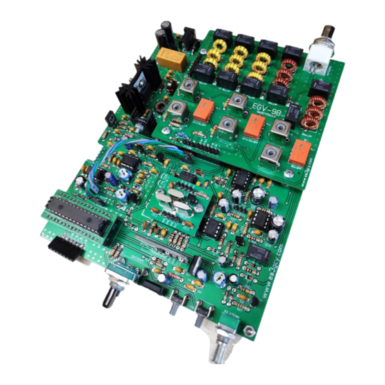
MAIN BOARD
Assembly manual
Last update March 01, 2023
ea3gcy@gmail.com
Latest updates and news in:
www.ea3gcy.com
EGV-9B
v1
Thank you for building the
80 to 10m QRP CW Transceiver kit
Have fun assembling it and enjoy QRP! 73 Javier Solans, EA3GCY
EGV-9B
80 to 10m QRP CW Transceiver Kit
Page 1
Advertisement

Summary of Contents for EA3GCY EGV-9B v1
- Page 1 Latest updates and news in: www.ea3gcy.com EGV-9B Thank you for building the 80 to 10m QRP CW Transceiver kit Have fun assembling it and enjoy QRP! 73 Javier Solans, EA3GCY EGV-9B 80 to 10m QRP CW Transceiver Kit Page 1...
- Page 2 Miguel EA3EGV was the founder member #1 of the EA-QRP CLUB. On September 1994 a group of four hams, Miguel Montilla EA3EGV, Miguel Molina EA3FHC, Vicenç Llario EA3ADV and myself, Javier Solans EA3GCY, founded the EA-QRP. EGV-9B The EGV-9B is the evolution of the legendary EGV+ kit.
-
Page 3: Specifications
Note: good experience on radio assembly is required. It shouldn't be your first transceiver to build. All SMD parts soldered at the factory. You don't have to solder anything SMD SPECIFICATIONS GENERAL: Frequency coverage: 80-60-40-30-20-17-15-12-10m Note: You can tune below and above the bands (from 3 to 30MHz) but downgrading the characteristics Tuning steps on two ranges: 10Hz-100Hz-1kHz and 10kHz-100kHz-1MHz. - Page 4 LIST OF COMPONENTS BY VALUE/QUANTITY Resistors list Value Checked Ref. Identified 10 Ω R7, R14, R46, R47 brown-black-black 22 Ω R23, R24, R32, R34 red-red-black 100 Ω R1, R2, R3, R8, R16, R19, R39, R45, R49, R50 brown-black-brown 150 Ω R15, R17 brown-green-brown 330 Ω...
- Page 5 Semiconductor list Type Checked Ref. Identified Transistors Q1, Q2, Q3, Q7, Q10, Q11, Q12, Q13, Q14, BC547 C547 Q15, Q16, Q17 2N7000 Q8, Q9 2N7000 BD140 BD135 or C2314 or NTE295 BD135 / C2314 / NTE295 BD140 2SC1969 SC1969 78L05 IC1, IC4 78L05 7809...
- Page 6 M3 washer Metal M3 washer to Q5 and Q6 M3 spacers Hex 10mm M3 spacers 60 cm. 60 cm. 0,4mm enamelled wire EGV-3B Main PCB (printed circuit board) EGV-9B v1 EGV-9B 80 to 10m QRP CW Transceiver Kit Page 6...
- Page 7 LIST OF INDIVIDUAL COMPONENTS Resistors Checked Ref. Value Ident./Comment Circuit section Located 100 Ω brown-black-brown Keyer 100 Ω brown-black-brown Keyer 100 Ω brown-black-brown Keyer brown-black-orange Keyer yellow-violet-red Sidetone yellow-violet-red Sidetone 10 Ω brown-black-black Sidetone N/O-1 100 Ω brown-black-brown Sidetone G-11 brown-black-orange Switches brown-black-red...
- Page 8 brown-black-orange Digital section Q/R-5 brown-black-orange Digital section Q/R-6 brown-black-orange Digital section brown-black-orange Digital section brown-black-orange Digital section J/I-7 brown-black-orange Digital section G/H-5 brown-black-orange Digital section G/H-6 brown-black-orange Digital section G/H-7 brown-black-orange Digital section G/H-7 brown-black-orange Digital section G/H-8 brown-black-orange Digital section G/H-9 Potentiometers list 10K adjustable 103 RM-065...
- Page 9 Semiconductors Checked Ref. Type Ident./Comment Circuit section Located Transistors BC547 BC547 Keyer BC547 BC547 Switches BC547 BC547 Switches N-12 BD140 BD140 CW TX key BD135 BD135 Driver J-3/4 2SC1969 C1969 Out. Amp. BC547 BC547 D-12 2N7000 2N7000 G-12 2N7000 2N7000 G-12 BC547 BC547...
- Page 10 252-QUADRANT COMPONENT LAYOUT MAP EGV-9B 80 to 10m QRP CW Transceiver Kit Page 10...
-
Page 11: Recommended Assembly Sequence
ASSEMBLY You can use the “individual parts list” or the “value/quantity parts list.” Using the “value/quantity parts list” is the quickest way to mount components since all the circuit board components of the same value or type can be placed one after the other. However, you will need the “individual parts list” to know how each component is identified and its location on the circuit board. - Page 12 There are three specific type diodes: D1 is a 47V zener diode. D2 is 6V2 zener diode D3 is a BY255 diode. 1N4148 diodes location map: EGV-9B 80 to 10m QRP CW Transceiver Kit Page 12...
- Page 13 apacitors There are ceramic and electrolytic capacitors. They all have their value printed on the body. Refer to the “identified” column in the parts list. When you mount them, make sure to leave the leads as short as possible. ...
- Page 14 100n capacitors location map: EGV-9B 80 to 10m QRP CW Transceiver Kit Page 14...
- Page 15 in headers and jumpers - Place and solder the 5-pin polarized header corresponding to the R, L paddles, CMD switch and GND. - Place and solder the 2 male pin “J1” ON/OFF. - Place and solder the two “BAND” 3 male pins strip. - Place and solder the P4 “VOLUME”...
- Page 16 Prepare Q5 and Q6, but do not place them yet. It is better to do it after placing L1 and L2. BD135 Mount Q5 onto the heatsink as shown in the image. Use a mica insulator sheet that you will find in the kit and trim it 1-2mm every side so that it seats well within the heatsink.
- Page 17 If you plan to work at maximum power and for long periods of time (at base station) it may be advisable to increase the cooling surface. You can add some system to increase the temperature dissipation, for example by an auxiliary metal surface, a mini-fan or other similar system. You can also screw the Q6 to the base of the metal case through the 6mm hole.
- Page 18 Mount the sockets for IC2, IC3, IC5, IC6, IC7, IC8, IC9 in the locations printed on the circuit board. Make sure that the sockets lie flat against the circuit board. Next, insert IC2, IC3, IC5, IC6, IC7, IC8, IC9 into their respective sockets.
- Page 19 IMPORTANT: Wind the toroid exactly as shown in the images. You must pay attention to number of turns as well as to the direction of the winding. oroid transformer L2 is an impedance matching transformer with a bifilar winding. An FT37-43 (black toroid with 9.5mm/0.375in outer diameter) is used.
- Page 20 - Cut the ends and separate the two windings. - Use a sharp knife to scrape the enamel off the ends that will be soldered. The ends of the coils that we have made need to be prepared in this manner before soldering them into the board. - Using a multimeter in its ohm or continuity function, locate and mark the ends, identifying them as “a”...
- Page 21 P3 RX otary NCODER, attenuator potentiometer, volume potentiometer, UP- DOWN band switches and external connections acks, (antenna, speaker, headphones, power supply) and the speaker-headphone witch Now mount and solder the Rotary Encoder, the P3 RX attenuator potentiometer (marked B1K) and UP and DOWN BAND switches on PCB in their respective locations.
- Page 22 IC12 SI5351 The IC12 is a module that incorporates the SI-5351 frequency generator Solder the elbow 7-pin strip and solder the module onto the board. Make sure that the module is vertically with the board as shown in the images. ...
- Page 23 IC14 ATMEGA328P module (Arduino NANO compatible) Install the two 15-pin female strips on EGV-3B board to ATMEGA328P or Arduino NANO module as shown in the image. To assemble the ATMEGA328P module follow the following order: - Solder the 28-pin IC socket. You must make sure to place it in the correct direction according to the silhouette printed on the board.
- Page 24 EGV-9B 80 to 10m QRP CW Transceiver Kit Page 24...
-
Page 25: Wiring And Connections
WIRING AND CONNECTIONS The EGV-9B requires wiring of the paddles, CMD push button, RX pass-band potentiometer. The EGV-9B requires wiring “VOLUME” and “V-TUNE” (Band tune) potentiometers. The EGV-9B circuit board incorporates the power, antenna, headphone, and external speaker and headphone jacks and “speaker/headphones”... - Page 26 ire paddle connector and “CMD” push-button On the EGV-9B PCB The paddles and the "CMD" command push-button connector has 5 pins: “R” (right paddle), “GND”, “L” (left paddle), “CMD” (command push-button) and “GND”. Note: this connector has two “GND” pins. The two are the same. On the small PCB for panel connection The small PCB incorporates the Jack for the paddles and the “CMD”...
- Page 27 EGV-9B enclosure It is highly recommended that suits a metal box for all items that are installed on the board. If you use a plastic box, then make RFI shield with conductive paint or conductive tape (aluminum or copper may be suitable). There is a custom box for the EGV-9B in www.qrphamradiokits.com The EGV-9B is protected against possible polarity reversal faults by means of diode D3 If your power supply is short-circuit protected or is equipped with a fuse at the output, perfect;...
- Page 28 SETTINGS AND TESTS irst checks - Adjust all adjustable resistors (P1, P2, P5) and P4 (volume potentiometer) to mid-position. - Adjust P3 (RX potentiometer) to maximum position (clockwise). - Plug a speaker into the "SPEAKER" jack or headphones into the "PHONES" jack. IMPORTANT: Use a good quality speaker unit.
- Page 29 - 80m band-pass filter. L1 and L2 adjust the band-pass for 80m, this setting is fixed and is not affected by the “band” tuning potentiometer (P1). With an antenna connected to the transceiver tune any frequency in the 80m and adjust L1 and L2 until you get the maximum signal level.
- Page 30 Plug in headphones and toggle the switch from Speaker to Headphones. Adjust the P6 to get the receive audio level you like best. Adjust the P7 to get the Sidetone level you like best. djustment of P2 TX to RX decay delay. Adjust to your liking, based on your CW speed ...
- Page 31 ANNEXES AND TIPS KB-2 Electronic KEYER. Please, download the “EGV-9B KB2 User Manual” from the website: www.qrphamradiokits.com ncreasing the AGC decay. The CAG decay time can be increased by changing the values of C13 and R31. Try increase R31 to 1M. This modification will depend on your listening habits. If you are satisfied with the current values, do not make the modification.
- Page 32 distortion. You can decrease the audio gain by increasing the value of R45, try 1K, this is especially useful if you often use headphones. Filter Bandwidth. You can increase or decrease the IF filter bandwidth by decreasing (wider) or increasing (narrower) the value of capacitors CFL1, CFL2, and CFL3.
-
Page 33: Limited Warranty
I can also supply any part that you have lost, Javier Solans, EA3GCY, warrants this device to damaged or broken accidently. function according to the specifications, provided If you find any errors in this manual or would like... - Page 34 SCHEMATICS EGV-9B 80 to 10m QRP CW Transceiver Kit Page 34...
- Page 35 EGV-9B 80 to 10m QRP CW Transceiver Kit Page 35...
Need help?
Do you have a question about the EGV-9B v1 and is the answer not in the manual?
Questions and answers