Table of Contents
Advertisement
Available languages
Available languages
Quick Links
WARNING: This appliance
is equipped for (Natural or Pro-
pane) gas. Field conversion is
not permitted.
CAUTION - FOR YOUR SAFETY
WARNING: IF THE INFORMATION IN THIS MANUAL IS NOT FOLLOWED
EXACTLY, A FIRE OR EXPLOSION MAY RESULT CAUSING PROPERTY
DAMAGE, PERSONAL INJURY OR LOSS OF LIFE.
- Do not store or use gasoline or other flammable vapors and Iiquids in vicinity of this or
any other appliance.
WHAT TO DO IF YOU SMELL GAS
• Do not try to light any appliance.
• Do not touch any electrical switch; do not use any phone in your building.
• Immediately call your gas supplier from a neighbor's phone. Follow the gas supplier's
instructions.
• If you cannot reach your gas supplier, call the fire department.
- Installation and service must be performed by a qualified installer, service agency or the
gas supplier.
This is an unvented gas-fired heater. It uses air (oxygen) from the room in which it is
installed. Provisions for adequate combustion and ventilation air most be provided.
Refer to Air For Combustion and Ventilation section on page 8-10 of this manual.
This appliance may be installed in an aftermarket, permanently located manufactured (mobile)
home, where not prohibited by local codes.
This appliance is only for use with the type of gas indicated on the rating plate.
This appliance is not convertible for use with other gases.
Questions, problems, missing parts? Before returning to your retailer, call our customer
service department at 1-877-447-4768, 8:30 a.m. – 4:30 p.m., CST, Monday – Friday or
email us at customerservice@ghpgroupinc.com.
INSTALLER: Leave this manual with the appliance.
CONSUMER: Retain this manual for future reference.
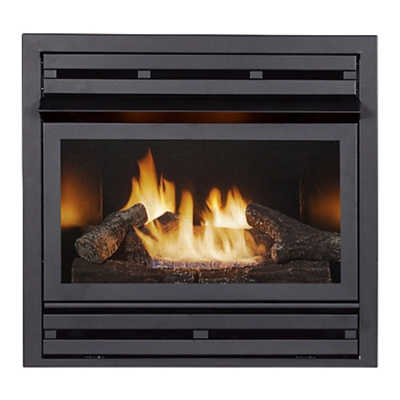
VENT-FREE FIREPLACE INSERT
1
Models:
Propane
PHZCI28LP
PHZCI32LP
Natural Gas
PHZCI28NG
PHZCI32NG
ANS Z21.11.2-2019
80-10-565 -
2022-12-08
Advertisement
Chapters
Table of Contents

Subscribe to Our Youtube Channel
Related Manuals for GHP Group Pleasant Hearth PHZCI28LP


Summary of Contents for GHP Group Pleasant Hearth PHZCI28LP
- Page 1 VENT-FREE FIREPLACE INSERT Models: Propane PHZCI28LP PHZCI32LP Natural Gas PHZCI28NG PHZCI32NG WARNING: This appliance is equipped for (Natural or Pro- pane) gas. Field conversion is not permitted. ANS Z21.11.2-2019 CAUTION - FOR YOUR SAFETY WARNING: IF THE INFORMATION IN THIS MANUAL IS NOT FOLLOWED EXACTLY, A FIRE OR EXPLOSION MAY RESULT CAUSING PROPERTY DAMAGE, PERSONAL INJURY OR LOSS OF LIFE.
-
Page 2: Table Of Contents
TABLE OF CONTENTS Specifications ........................... 2 Important Safety Information ......................3 Product Identification ........................5 Product Features ..........................7 Preparing for Installation........................8 Installation ............................11 Operation ............................26 Care and Maintenance ........................29 Troubleshooting ..........................31 Replacement Parts ......................... 34 Accessories ............................ -
Page 3: Important Safety Information
IMPORTANT SAFETY INFORMATION IMPORTANT: Read this owner’s manual carefully and completely before trying to assemble, operate, or service this heater. Improper use of this heater can cause serious injury or death from burns, fire, explosion, electrical shock, and carbon monoxide poisoning. WARNING: Installation and repair should be done by a qualified service person. - Page 4 SAFETY INFORMATION 1. This appliance is only for use with the type of gas indicated on the rating plate. This appliance is not convertible for use with other gases. 2. Do not place propane/LP supply tank(s) inside any structure. Locate propane/LP supply tank(s) outdoors. 3.
-
Page 5: Product Identification
PRODUCT IDENTIFICATION PHZCI28LP PHZCI32LP PHZCI28NG PHZCI32NG Fireplace Insert Cabinet Stando s Stando s Hood Stando s Stando s Stando s Screen Ignitor Button Control Knob Ignitor Button Control Knob Fig. 1 - Vent-Free Fireplace Insert Fig. 1.1 - Standoffs... - Page 6 Fig. 1.2 - PHZCI28LP/PHZCI28NG Fig. 1.3 - PHZCI32LP/PHZCI32NG...
-
Page 7: Product Features
PRODUCT FEATURES SAFETY PILOT This heater has a pilot with an Oxygen Depletion Sensing (ODS) safety shutoff system. The ODS/pilot shuts off the heater if there is not enough fresh air and cuts off main burner gas in the event of flame out. ELECTRIC PUSH BUTTON IGNITION SYSTEM This heater is equipped with an electronic piezo control system. -
Page 8: Preparing For Installation
PREPARING FOR INSTALLATION AIR FOR COMBUSTION AND VENTILATION WARNING: This heater shall not be installed in a room or space unless the required volume of indoor combustion air is provided by the method described in the Nation Fuel Gas Code, ANSI Z223.1/NFPA 54, the International Fuel Gas Code, or applicable local codes. - Page 9 PREPARING FOR INSTALLATION DETERMINING FRESH-AIR FLOW FOR HEATER LOCATION Determining if You Have a Confined or Unconfined Space Use this worksheet to determine if you have a confined or unconfined space. Space: Includes the room in which you will install heater plus any adjoining rooms with doorless passageways or ventilation grills between the rooms.
- Page 10 PREPARING FOR INSTALLATION Ventilation Air From Inside Building This fresh air would come from adjoining unconfined space. When ventilating to an adjoining unconfined space, you must provide two permanent openings: one within 12 in. of the wall connecting the two spaces (see options 1 and 2, Fig.
-
Page 11: Installation
2. Remove all protective packaging applied to fireplace for shipment. 3. Make sure your fireplace includes one hardware packet. 4. Check fireplace for any shipping damage. If fireplace is damaged, call GHP Group, Inc., at 1-877- 447-4768. Please do not return it to the store. - Page 12 INSTALLATION FIREPLACE CLEARANCES CAUTION: If you install the fireplace in a home garage • fireplace pilot and burner must be at least 18" above floor. • locate fireplace where moving vehicle will not hit it. For convenience and efficiency, install fireplace •...
- Page 13 INSTALLATION BUILT IN FIREBOX ENCLOSURE Wall Stud WARNING: Do not allow any 12” combustible materials to overlap the 10” Drywall Board firebox front. 8” Wall Stud 6” WARNING: Do not allow 2.5” 23" 21" combustible or noncombustible 19" Drywall Board 16"...
- Page 14 INSTALLATION BUILT IN FIREBOX INSTALLATION WARNING: This optional blower is equipped with a three-prong (grounding) plug for your protection against shock hazard and must be plugged directly into a properly grounded three-prong receptacle. Firebox must be disconnected from gas supply and removed from mantel before installing fan accessory.
- Page 15 INSTALLATION DISASSEMBLY WARNING: Always have screen in place before operating firebox insert. This prevents excessive temperatures on fireplace surfaces. WARNING: Failure to position the parts in accordance with these diagrams or failure to use only parts specifically approved with this fireplace may result in property damage or personal injury.
- Page 16 INSTALLATION BLOWER INSTALLATION (OPTIONAL) NOTE: If any of the original wire as supplied with the appliance must be replaced, it must be replaced with a wire of at least an equal temperature rating. NOTE: Installation may require two people. CAUTION: Label all wires prior to disconnection when servicing controls. Wiring errors can cause improper and dangerous operation.
- Page 17 INSTALLATION 4. Reinsert fan and bracket assembly into the Top Vent and screw in x 4 screws into the back of the fireplace cabinet. Screws Screws 5. Route the fan cable through the race way. Note: Junction box needs an outlet installed. BLOWER WIRING DIAGRAM GREEN/VERDE BLOWER...
- Page 18 INSTALLATION CONNECTING TO GAS SUPPLY WARNING: A qualified service technician must connect heater to gas supply. Follow all local codes. CAUTION: Never connect heater directly to the gas supply. This heater requires an external regulator (not supplied). The external regulator between the gas supply and heater must be installed. Gas supplier provides external regulator for natural gas.
- Page 19 INSTALLATION CAUTION: Use pipe joint sealant that is resistant to gas (PROPANE or NG). We recommend that you install a sediment trap in a supply line as shown in Fig. 10. Locate sediment trap where it is within reach for cleaning and not likely to freeze. Install in the piping system between fuel supply and heater.
- Page 20 INSTALLATION WALL INSTALLATION 1. Adjust the standoffs to the wall thickness. LACE INSTALLATION ND THE EDGE OF 2. Carefully lift the insert through the center opening in the front of the wall. Slide the insert back through the opening until the metal trim 7 INCH makes contact with the front of the wall.
- Page 21 INSTALLATION REASSEMBLY WARNING: Always have screen in place before operating firebox insert. This prevents excessive temperatures on fireplace surfaces. WARNING: Failure to position the parts in accordance with these diagrams or failure to use only parts specifically approved with this fireplace may result in property damage or personal injury.
- Page 22 INSTALLATION ASSEMBLING LOGS PHZCI28LP PHZCI28NG WARNING: Failure to position the parts in accordance with these diagrams or failure to use only parts specifically approved with this heater may result in property damage or personal injury. CAUTION: After installation and peridically thereafter, check to ensure that no yellow flame comes in contact with any log.
- Page 23 INSTALLATION ASSEMBLING LOGS PHZCI32LP PHZCI32NG WARNING: Failure to position the parts in accordance with these diagrams or failure to use only parts specifically approved with this heater may result in property damage or personal injury. CAUTION: After installation and peridically thereafter, check to ensure that no yellow flame comes in contact with any log.
- Page 24 INSTALLATION WIRING DIAGRAM WARNING: Never connect valve to line voltage. Failure to follow this will result in damage to equipment and could result in severe injury or death. WIRING INSTRUCTIONS: Follow the wiring instructions furnished by the appliance manufacturer, if available, or use the following general instructions.
- Page 25 INSTALLATION CHECKING GAS CONNECTIONS WARNING: Test all gas piping and connections for leaks after installing or servicing. Correct all leaks immediately. WARNING: Never use an open flame to check for a leak. Apply a mixture of liquid soap and water to all joints.
-
Page 26: Operation
OPERATION FOR YOUR SAFETY READ BEFORE LIGHTING WARNING: If you do not follow these instructions exactly, a fire or explosion may result causing property damage, personal injury or loss of life. A. This appliance has a pilot which must be lighted by the electronic ignitor. When lighting the pilot, follow these instructions exactly. - Page 27 OPERATION LIGHTING INSTRUCTIONS Start-up Procedure 1. STOP! Read the safety information to the left on this label. 2. Open the lower access panel located below the fireplace screen. 3. Set the room thermostat, if present, to the lowest level. Set the wall switch, if present, to its off position.
- Page 28 OPERATION INSPECTING BURNERS Check pilot flame pattern and burner flame patterns often. PILOT FLAME PATTERN Figure 20 shows a correct pilot flame pattern. Figure 21 shows an incorrect pilot flame pattern. The incorrect pilot flame is not touching the thermocouple. This will cause the thermocouple to cool. When the thermocouple cools, the fireplace will shut down.
-
Page 29: Care And Maintenance
CARE AND MAINTENANCE BURNER FLAME PATTERN Figure 22 shows a correct burner flame pattern. Figure 23 shows an incorrect burner flame pattern. The incorrect burner flame pattern shows sporadic, irregular flame tipping. The flame should not be dark or have an orange/reddish tinge. Note: When using the fireplace the first time, the flame will be orange for approximately one hour until the log cures. - Page 30 CARE AND MAINTENANCE 1. Shut off unit including pilot. Allow unit to cool for at least 30 minutes. 2. Inspect burner, pilot and primary air inlet holes on orifice holder for dust and dirt (See Fig. 24). 3. Blow air through the ports/slots and holes in the burner. 4.
-
Page 31: Troubleshooting
TROUBLESHOOTING WARNING: If you smell gas: • Shut off gas supply. • Do not try to light any appliance. • Do not touch any electrical switch; do not use any phone in your building. • Immediately call your gas supplier from a neighbor’s phone. Follow the gas supplier’s instructions. •... - Page 32 TROUBLESHOOTING PROBLEM POSSIBLE CAUSE CORRECTIVE ACTION 1. Control knob is not fully ODS/pilot lights 1. Press in control knob fully. pressed in. but flame goes out 2. Control knob is not pressed when control knob is 2. After ODS/pilot lights, keep control in long enough.
- Page 33 TROUBLESHOOTING PROBLEM POSSIBLE CAUSE CORRECTIVE ACTION White powder resi- 1. When heated, the vapors 1. Turn heater off when using furniture due forming within from furniture polish, wax, polish, wax, carpet cleaner or similar burner box or on carpet cleaners, etc., turn products.
-
Page 34: Replacement Parts
REPLACEMENT PARTS For replacement parts, call our customer service department at 1-877-447-4768, 8:30 a.m. – 4:30 p.m., CST, Monday – Friday. FIREBOX MODELS PHZCI28LP, PHZCI28NG, PHZCI32LP, PHZCI32NG Firebox Top Grille Hood Screen PART NUMBER ITEM DESCRIPTION PHZCI28LP PHZCI32LP PHZCI28NG PHZCI32NG TOP GRILLE 700-M1014B 700-L1014B... -
Page 35: Accessories
REPLACEMENT PARTS LIST For replacement parts, call our customer service department at 1-877-447-4768, 8:30 a.m. – 4:30 p.m., CST, Monday – Friday. PHZCI28LP PHZCI32LP PHZCI28NG PHZCI32NG PART NUMBER ITEM DESCRIPTION PHZCI28LP PHZCI32LP PHZCI28NG PHZCI32NG LOG SET (COMPLETE) 700-M1018 700-L1018 LOG 1 700-M1018-01 700-L1018-01 LOG 2... -
Page 37: Warranty
This limited warranty is extended to the original retail purchaser of this heater and warrants against any years years... - Page 38 GHP Group, Inc. 6440 W Howard St Niles, IL 60714-3302 Tel: (877) 447-4768 www.ghpgroupinc.com GHP Group, Inc. 6440 W Howard St Niles, IL 60714-3302...
- Page 39 INSERTO DE CHIMENEA SIN SALIDA AL EXTERIOR Modelos: Propano PHZCI28LP PHZCI32LP Gas Natural PHZCI28NG PHZCI32NG ADVERTENCIA: Este aparato está equipado para gas (Natural o Propano). La conversión de campo no está permitida. ANS Z21.11.2-2019 PRECAUCIÓN- PARA SU SEGURIDAD ADVERTENCIA: SI NO SE SIGUE CON EXACTITUD LA INFORMACIÓN EN ESTE MANUAL, PUEDE RESULTAR UN INCENDIO O EXPLOSIÓN OCASIONANDO DAÑOS A LA PROPIEDAD, LESIONES PERSONALES O LA MUERTE.
-
Page 40: Epecificaciones
TABLA DE CONTENIDO Epecificaciones..........................40 Información de seguridad importante .....................41 Identificación del producto ......................43 Características del producto ......................45 Preparación para la instalación ...................... 46 Instalación ............................49 Operación ............................63 Cuidado y mantenimiento ....................... 67 Resolución de fallas ........................69 Piezas de repuesto ......................... -
Page 41: Información De Seguridad Importante
INFORMACIÓN DE SEGURIDAD IMPORTANTE IMPORTANTE: Lea este manual del propietario cuidadosa y completamente antes de intentar ensamblar, op- erar o reparar este calefactor. El uso inadecuado de este calefactor puede causar lesiones graves o la muerte por quemaduras, incendios, explosiones, descargas eléctricas e intoxicación por monóxido de carbono. ADVERTENCIA: La instalación y reparación deben ser realizadas por personal de servicio calificado. - Page 42 INFORMACIÓN DE SEGURIDAD 1. Este aparato es solo para ser usado con el tipo de gas indicado en la placa de características. Este aparato no es convertible para uso con otros gases. 2. No coloque el(los) tanque(s) de suministro de propano/PL dentro de ninguna estructura. Coloque el(los) tanque(s) de suministro de propano/PL en exteriores.
-
Page 43: Identificación Del Producto
IDENTIFICACIÓN DEL PRODUCTO PHZCI28LP PHZCI32LP PHZCI28NG PHZCI32NG Mueble para el inserto de Separadores Fireplace Insert Cabinet Stando s la chimenea Separadores Stando s Hood Campana Separadores Stando s Separadores Stando s Separadores Stando s Screen Pantalla Ignitor Button Botón de encendido Perilla de control Control Knob Ignitor Button... - Page 44 Fig. 1.2 - PHZCI28LP/PHZCI28NG Fig. 1.3 - PHZCI32LP/PHZCI32NG...
-
Page 45: Características Del Producto
CARACTERÍSTICAS DEL PRODUCTO PILOTO DE SEGURIDAD Este calefactor tiene un piloto con un sistema de apagado de seguridad de Detección de dis- minución de oxígeno (ODS). El ODS/piloto apaga el calefactor si no hay suficiente aire fresco y corta el gas del quemador principal en el caso de que la llama se apague. SISTEMA DE IGNICIÓN ELÉCTRICA DE BOTÓN DE PRESIÓN Este calefactor está... -
Page 46: Preparación Para La Instalación
PREPARACIÓN PARA LA INSTALACIÓN AIRE PARA LA COMBUSTIÓN Y VENTILACIÓN ADVERTENCIA: Este calefactor no deberá ser instalado en una habitación o espacio a menos que el volumen requerido de aire de combustión de interiores sea proporcionado por el método de- scrito en el Código Nacional de Gas Combustible, ANSI Z223.1/NFPA 54, el Código Internacional de Gas Combustible, o códigos locales aplicables. - Page 47 PREPARACIÓN PARA LA INSTALACIÓN DETERMINACIÓN DEL FLUJO DE AIRE FRESCO A LA UBICACIÓN DEL CALEFACTOR Determinación de si tiene un espacio confinado o no confinado Use esta hoja de cálculo para determinar si tiene un espacio confinado o no confinado. Espacio: Incluye la habitación en la cual instalará...
- Page 48 PREPARACIÓN PARA LA INSTALACIÓN Aire de ventilación desde el interior del edificio Este aire fresco vendría del espacio no confinado contiguo. Cuando se ventila a un espacio no 12 pulg. confinado contiguo, debe proporcionar dos aberturas permanentes: una dentro de 12 pulg.
-
Page 49: Instalación
3. Asegúrese de que su chimenea incluya un paquete de herrajes. 4. Revise la chimenea para detectar cualquier daño producido durante el envío. Si la chimenea está dañada, llame a GHP Group, Inc., al 1-877-447-4768. Por favor, no la devuelva a la tienda. Herramientas requeridas: •... - Page 50 INSTALACIÓN ESPACIOS LIBRES DE LA CHIMENEA PRECAUCIÓN: Si instala la chimenea en la cochera de su casa • el piloto y el quemador de la chimenea deben estar al menos a 18" sobre el piso. • coloque la chimenea donde vehículos en movimiento no la golpeen. Por conveniencia y eficiencia, instale la chimenea •...
- Page 51 INSTALACIÓN CARCASA INTEGRADA DE LA CÁMARA DE COMBUSTIÓN Wall Stud Montante de la pared ADVERTENCIA: No permita que ningún 12” material combustible se superponga al 10” Drywall Board Tablero de tabiquería seca frente de la cámara de combustión. 8” Wall Stud 6”...
- Page 52 INSTALACIÓN INSTALACIÓN DE LA CÁMARA DE COMBUSTIÓN INTEGRADA ADVERTENCIA: Este soplador opcional está equipado con un enchufe de tres clavijas (conexión a tierra) para su protección contra el riesgo de electrocución y debe enchufarse directamente a un receptáculo de tres clavijas correctamente conectado a tierra. La cámara de combustión debe desconectarse del suministro de gas y retirarse de la repisa antes de instalar el accesorio del ventilador.
- Page 53 INSTALACIÓN DESMONTAJE ADVERTENCIA: Siempre tenga la pantalla en su lugar antes de poner en funcionamien- to el inserto de la cámara de combustión. Esto previene las temperaturas excesivas en las superficies de la chimenea. ADVERTENCIA: Si no se colocan las piezas de acuerdo con estos diagramas o no se uti- lizan solo las piezas específicamente aprobadas para esta chimenea, pueden provocar daños a la propiedad o lesiones personales.
- Page 54 INSTALACIÓN BLOWER INSTALLATION (OPTIONAL) NOTA: si se debe reemplazar alguno de los cables originales suministrados con el artefac- to, debe reemplazarse con un cable que soporte por lo menos una temperatura igual. NOTA: La instalación puede requerir dos personas. PRECAUCIÓN: etiquete todos los cables antes de desconectarlos durante el mantenimiento de los controles.
- Page 55 INSTALACIÓN 4. Vuelva a insertar el ensamblaje del ventilador y el soporte en la ventilación superior y atornille los 4 tornillos que retiró anteriormente en la parte posterior Screws del gabinete de la chimenea. Screws 5. Pase el cable del soplador a través de la vía de rodadura.
- Page 56 INSTALACIÓN CONEXIÓN AL SUMINISTRO DE GAS ADVERTENCIA: Un técnico de servicio calificado debe conectar el calefactor al suministro de gas. Siga todos los códigos locales. PRECAUCIÓN: Nunca conecte el calefactor directamente al suministro de gas. Este calefactor requiere un regulador externo (no suministrado). El regulador externo entre el suministro de gas y el calefactor debe ser instalado.
- Page 57 INSTALACIÓN PRECAUCIÓN: Use sellador de juntas de tubo que sea resistente al gas (PROPANO O GN). Recomendamos una trampa de sedimentos en una línea de suministro como se muestra en la Fig. 10. Ubique la trampa de sedimentos donde esté al alcance para limpieza y que no existan probabilidades de que se congele. Instálela en el sistema de tuberías entre el suministro de combustible y el calefactor.
- Page 58 INSTALACIÓN INSTALACIÓN EN PARED 1. Ajuste los separadores al grosor de la pared. LACE INSTALLATION ND THE EDGE OF 2.Levante el inserto cuidadosamente a través de la abertura central en la parte frontal de la pared. Deslice el inserto hacia atrás a través de 7 INCH la abertura hasta que el borde metálico haga contacto con la parte frontal de la pared.
- Page 59 INSTALACIÓN REENSAMBLAJE ADVERTENCIA: Siempre tenga la pantalla en su lugar antes de poner en funcionamien- to la cámara de combustión. Esto previene las temperaturas excesivas en las superfi- cies de la chimenea. ADVERTENCIA: Si no se colocan las piezas de acuerdo con estos diagramas o no se uti- lizan solo las piezas específicamente aprobadas para esta chimenea, pueden provocar daños a la propiedad o lesiones personales.
- Page 60 INSTALACIÓN ENSAMBLAJE DE LOS LEÑOS PHZCI28LP PHZCI28NG ADVERTENCIA: No colocar las piezas de acuerdo con estos diagramas o no usar solamente piezas específicamente aprobadas con este calefactor puede resultar en daños a la propiadad o lesiones personales. PRECAUCIÓN: Después de la instalación y a partir de alli periódicamente, revise para asegurarse de que ninguna llama amarilla entre en contacto con los leños.
- Page 61 INSTALACIÓN ENSAMBLAJE DE LOS LEÑOS PHZCI32LP PHZCI32NG ADVERTENCIA: No colocar las piezas de acuerdo con estos diagramas o no usar solamente piezas específicamente aprobadas con este calefactor puede resultar en daños a la propiadad o lesiones personales. PRECAUCIÓN: Después de la instalación y a partir de alli periódicamente, revise para asegurarse de que ninguna llama amarilla entre en contacto con los leños.
- Page 62 INSTALACIÓN DIAGRAMA DE CABLEADO DIAGRAMA DE CABLEADO DE LA VERSIÓN "MILIVOLTIOS PLUS” Quemador piloto Termostato de ambiente ADVERTENCIA: Nunca conecte la válvula al voltaje de la línea. De lo contrario, se producirán daños al equipo y pueden ocasionar lesiones graves o la muerte. INSTRUCCIONES DE CABLEADO: Siga las instrucciones de cableado proporcionadas por el fabricante del electrodoméstico, si están disponibles, o utilice las siguientes instrucciones generales.
- Page 63 INSTALACIÓN REVISIÓN DE LAS CONEXIONES DE GAS ADVERTENCIA: Pruebe toda la tubería y conexiones de gas en contra de fugas después de la instalación y el servicio. Corrija todas las fugas de inmediato. ADVERTENCIA: Nunca use una llama abierta para revisar en busca de fugas. Aplique una mezcla de jabón líquido y agua en todas las juntas.
-
Page 64: Operación
OPERACIÓN PARA SU SEGURIDAD LEA ANTES DEL ENCENDIDO ADVERTENCIA: Si no sigue estas instrucciones exactamente, puede resultar un incendio o explosión ocasionando daños a la propiedad, lesiones personales o la muerte. A. Este aparato tiene una piloto que debe ser encendido por el encendedor electrónico. Cuando encienda el piloto, siga estas instrucciones exactamente. - Page 65 OPERACIÓN INSTRUCCIONES DE ENCENDIDO Procedimiento de puesta en marcha 1.¡DETÉNGASE! Lea la información de seguridad a la izquierda en esta etiqueta. 2. Abra el panel de acceso inferior ubicado debajo de la pantalla de la chimenea. 3. Ajuste el termostato de la habitación, si está presente, al nivel más bajo.
- Page 66 OPERACIÓN INSPECCIÓN DE LOS QUEMADORES Revise con frecuencia el patrón de la llama del piloto y los patrones de la llama del quemador. PATRÓN DE LA LLAMA DEL PILOTO La Figura 20 muestra un patrón correcto de la llama del piloto. La Figura 21 muestra un patrón incor- recto de la llama del piloto.
-
Page 67: Cuidado Y Mantenimiento
CUIDADO Y MANTENIMIENTO PATRÓN DE LA LLAMA DEL QUEMADOR La Figura 22 muestra un patrón correcto de la llama del quemador. La Figura 23 muestra un patrón incorrecto de la llama del quemador. El patrón incorrecto de la llama del quemador muestra puntas de llama esporádicas e irregulares. - Page 68 CUIDADO Y LIMPIEZA 1. Apague la unidad incluyendo el piloto. Deje que la unidad se enfríe durante 30 minutos. 2. Inspeccione el quemador, el piloto y los agujeros de entrada de aire primario en el porta orificio en busca de polvo y suciedad (Ver Fig. 24). 3.
-
Page 69: Resolución De Fallas
RESOLUCIÓN DE FALLAS ADVERTENCIA: Si huele gas: • Apague el suministro de gas • No trate de encender ningún aparato. • No toque ningún interruptor eléctrico; no use ningún teléfono en su edificio. • LLame de inmediato a su proveedor de gas del teléfono de un vecino. Siga las instrucciones del proveedor de gas. - Page 70 RESOLUCIÓN DE FALLAS PROBLEMA CAUSA POSIBLE ACCIÓN CORRECTIVA 1. La perilla de control no está El ODS/piloto enciende 1. Oprima por completo la perilla de control completamente presionada. pero la llama se apaga 2. La perilla de control no está cuando la perilla de 2.
- Page 71 RESOLUCIÓN DE FALLAS PROBLEMA CAUSA POSIBLE ACCIÓN CORRECTIVA Residuo de polvo blanco 1. Cuando se calientan, los vapores 1. Apague el calefactor cuando use que se forma dentro de del pulidor de muebles, cera, pulidor de mueble, cera, limpiador de alfombra o la caja del quemador o limpiadores de alfombra, ect.
-
Page 72: Piezas De Repuesto
PIEZAS DE REPUESTO Para piezas de repuesto, llame a nuestro departamento de servicio al cliente al 1-877-447-4768, de lunes a viernes, de 8:30 a.m. a 4:30 p.m., hora estándar del Centro. MODELOS DE CAJA DE FUEGO PHZCI28LP, PHZCI28NG, PHZCI32LP, PHZCI32NG Cámara de combustión Rejilla superior Capucha... -
Page 73: Accesorios
LISTA DE PIEZAS DE REPUESTO Para piezas de repuesto, llame a nuestro departamento de servicio al cliente al 1-877-447-4768, de lunes a viernes, de 8:30 a.m. a 4:30 p.m., hora estándar del Centro. PHZCI28LP PHZCI32LP PHZCI28NG PHZCI32NG NÚM DE PIEZA NÚM DE DESCRIPCIÓN PHZCI28LP... -
Page 75: Garantía
Esta garantía limitada se extiende al comprador original al por menor de este conjunto de calentador y garantiza contra cualquier defecto en materiales y mano de obra durante un periodo de (2) años a par tir de la fecha de venta al por menor. GHP Group, Inc., a su opción, proporcionará... - Page 76 (14) después de la fecha de compra También puede registrar su garantíaen internet en www.ghpgroupinc.com. Complete el número de serie. Conserve esta porción de la tarjeta para sus registros. GHP Group, Inc. Inc. GHP Group, 6440 W Howard St 8280 Austin Ave.
Need help?
Do you have a question about the Pleasant Hearth PHZCI28LP and is the answer not in the manual?
Questions and answers