Advertisement
Quick Links
TIP Thüringer Industrie Produkte GmbH
Bahnhofstraße 26 • 99842 Ruhla • GERMANY • Tel. : +49 (0)36929/64029-0 • Fax : +49 (0)36929/64029-99 • info@stromzaehler.de • www.stromzaehler.de
NOVA RS485 MOD-BUS
RS485 Kommunikationsmodul - RS485 communication module
D
- BEDIENUNGSANLEITUNG
GB
- U S E R M A N U A L
ACHTUNG!
Die Installation und Inbetriebnahme des Zählers darf nur von ausgebildeten
Fachkräften durchgeführt werden. Vor jeder Tätigkeit am Gerät muß die
Versorgung getrennt werden.
WARNING!
Device installation and use must be carried out only by qualified staff.
Switch off the voltage before device installation.
ABMESSUNGEN (mm)
SIZE (mm)
90
25
44
18
KABEl-ABISolIERläNGE
CABlE STRIPPING lENGTH
Verdrahtung an den Klemmen
Terminals connection
0,5 Nm
5 mm
Ein 0,8x3,5 mm Flachschraubendreher anwenden
Use a blade screwdriver with 0.8x3.5 mm size
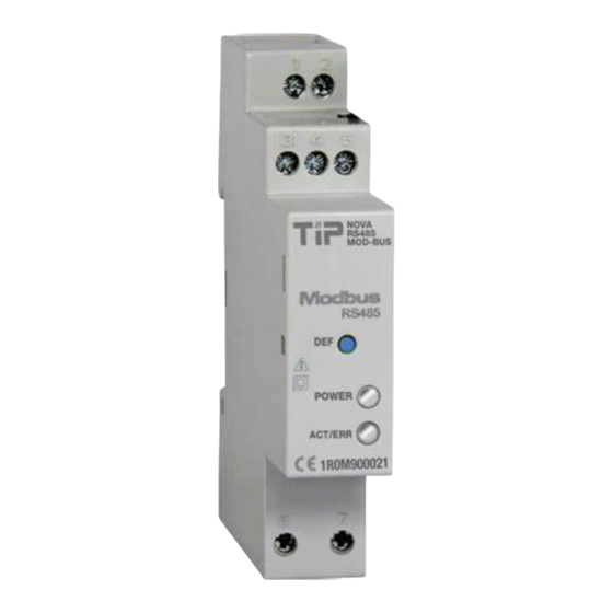
ÜBERSICHT
oVERVIEW
FUNKTIoN WERKSEINSTEllUNG
SET DEFAUlT FUNCTIoN
DEUTSCH
D
Die Funktion WERKSEINSTELLUNG dient zum Rücksetzen aller Einstellungen und stellt die
Werkseinstellungen ein (z.B. wenn die MODBUS Adresse vergessen wird).
Um die Werkseinstellung durchzuführen soll die Taste WERKSEINSTELLUNG mindestens 5 s ausgedrückt
werden, dann wird das Kommunikationsled Grün/Rot für 5 s blinken. Nach der Werkseinstellung wird
das Kommunikationsled ständig Rot sein, damit die Taste erlösen wird.
* 8N1=RTU Modus; 7E2=ASCII Modus
ENGLISH
GB
SET DEFAULT function allows to restore on the module default settings (e.g. in case of MODBUS
45
address forgotten).
To restore default settings, keep SET DEFAULT key pressed for at least 5 s, communication LED will blink
green/red for 5 s. At the end of SET DEFAULT procedure, communication LED will be red continuously
indicating to release the key.
* 8N1=RTU mode; 7E2=ASCII mode
EINSTEllUNGEN
65
SETTINGS
RS485 Kommunikationsgeschwindigkeit
RS485 communication speed
RS485 Modus
RS485 mode
MODBUS Adresse
MODBUS address
DEUTSCH
D
1.
Klemmen brücken zum Einschlaten des Terminationswiederstandes (RT)
2.
Klemmen zum RS485 Anschluss
3.
Infrarot-Schnittstelle
4.
Taste WERKSEINSTELLUNG
5.
LED der Hilfsspannung
6.
LED der Kommunikation
7.
Hilfspannunsklemmen
ENGLISH
GB
1.
Terminals to be jumpered for termination resistor (RT) enabling
2.
RS485 connection terminals
3.
Optical COM port
SET DEFAULT key
4.
5.
Power supply LED
6.
Communication LED
7.
Power supply terminals
WERKSEINSTEllUNGEN
DEFAUlT VAlUES
19200 bps
8N1*
01
lED FUNKTIoN
lEDS FUNCTIoNAlITY
Die zwei LED befinden sich auf die Frontseite des Moduls zur Anzeige des Versorgungs- und
Kommunikationsstandes.
Two LEDs are available on the module front panel to provide power supply and communication
status.
DEUTSCH
D
lED FARBE
MElDUNG
BEDEUTUNG
lED DER HIlFSSPANNUNG
-
Ausgeschaltet
Ausgeschaltetes Modul
GRÜN
Immer angeschaltet
Eingeschaltetes Modul
lED DER KoMMUNIKATIoN
-
Ausgeschaltet
Ausgeschaltetes Modul
Langsam blinkend
RS485 Kommunikation=OK
GRÜN
(jede 2 s aus)
Kommunikation zum Zähler=OK
Schnell blinkend
RS485 Kommunikation=fehlende/fehlerhaft
ROT
(jede 1 s aus)
Kommunikation zum Zähler=OK
ROT
Immer angeschaltet
Kommunikation zum Zähler=fehlende/fehlerhaft
GRÜN/ROT
Wechselfarben für 5 s
Laufende Werkseinstellung
ENGLISH
GB
lED ColoUR
SIGNAllING
MEANING
PoWER SUPPlY lED
-
Power OFF
The module is OFF
GREEN
Always ON
The module is ON
CoMMUNICATIoN lED
Power OFF
The module is OFF
-
Slow blink
RS485 communication=OK
GREEN
(2 s OFF time)
Counter communication=OK
Fast blink
RS485 communication=fault/missing
RED
(1 s OFF time)
Counter communication=OK
RED
Always ON
Counter communication=fault/missing
GREEN/RED
Alternating colours for 5 s
SET DEFAULT procedure in progress
Advertisement

Summary of Contents for TIP NOVA RS485 MOD-BUS
- Page 1 Two LEDs are available on the module front panel to provide power supply and communication TIP Thüringer Industrie Produkte GmbH Bahnhofstraße 26 • 99842 Ruhla • GERMANY • Tel. : +49 (0)36929/64029-0 • Fax : +49 (0)36929/64029-99 • info@stromzaehler.de • www.stromzaehler.de Klemmen brücken zum Einschlaten des Terminationswiederstandes (RT)
- Page 2 VERDRAHTUNG TECHNISCHE EIGENSHAFTEN CoNNECTIoNS TECHNICAl FEATURES BRÜCKE ZUM RT EINSCHAlTEN DEUTSCH WANDLER JUMPER FoR RT ENABlING RS232/USB CONVERTER Angaben gemäß der Richtlinie EIA RS485. HILfSSpaNNUNG Nennspannung: 230 V ±20% / 50 Hz Max Wiederholspannung: 300 V max 32 Module Max nicht Wiederholspannung Spitzenwert: 320 V (20 ms) REPEATER max 32 modules...
Need help?
Do you have a question about the NOVA RS485 MOD-BUS and is the answer not in the manual?
Questions and answers