Table of Contents
Advertisement
Quick Links
Advertisement
Table of Contents

Related Manuals for Dolby Laboratories 126


Summary of Contents for Dolby Laboratories 126
- Page 1 Dolby System 126 Owner's Manual 1 April 2023 Issue 1 Part number: 8800329...
- Page 2 Dolby Laboratories, Inc. 1275 Market Street San Francisco, CA 94103-1410 USA Telephone 415-558-0200 Fax 415-645-4000 http://www.dolby.com Trademarks Dolby and the double-D symbol are registered trademarks of Dolby Laboratories. The following are trademarks of Dolby Laboratories: Dialogue Intelligence Dolby Theatre ™ ® Dolby Dolby Vision ®...
-
Page 3: Table Of Contents
CS126MH key features and benefits..................... 8 CS128LF key features and benefits....................... 9 System 126 preinstallation information ....................10 2.4.1 System 126 screen placement and acoustic center information ..........10 2.4.2 System 126 configuration modes....................12 Selecting the wire for System 126......................13 GLL format files for software simulation modeling................ -
Page 4: Important Safety And Regulatory Information
Keep speakers out of extended or intense direct sunlight. Premature product failure or serious personal injury could occur if this product is used outdoors or in wet indoor environments. Dolby System 126 Owner's Manual Issue 1 Part number: 8800329 1 April 2023... - Page 5 Always be careful when moving the CS128LF or the assembled Dolby System 126 and employ at least two people when attempting any relocation of the speakers, as there is danger of tipping if the system is not secured to the building structure.
- Page 6 For additional information regarding Waste Electrical and Electronic Equipment (WEEE) and product disposal go to http:// www.dolby.com/us/en/about/environmental-commitment.html. CID1027 EAC RoHS information Product model CID1027 complies with EAC RoHS requirements. Dolby System 126 Owner's Manual Issue 1 Part number: 8800329 1 April 2023...
-
Page 7: Introduction To Dolby System 126
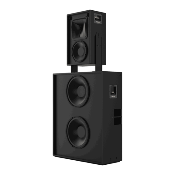
Introduction to Dolby System 126 Introduction to Dolby System 126 The Dolby System 126 is designed to meet the needs of a high-performance screen speaker in small to medium Dolby Atmos or 7.1 Cinemas, especially those rooms with minimal space behind the screen. -
Page 8: About This Documentation
Introduction to Dolby System 126 2.1 About this documentation This documentation describes the key features and benefits of Dolby System 126 and shows you how to install the system in a typical cinematic exhibition environment. 2.2 CS126MH key features and benefits The Dolby System 126 utilizes one CS126MH unit, which consists of an asymmetrical high-frequency horn with a high-performance transducer, and a low-distortion 10-inch midrange driver. -
Page 9: Cs128Lf Key Features And Benefits
CS128LF key features and benefits Figure 3: Dolby asymmetrical horn coverage 2.3 CS128LF key features and benefits Dolby System 126 utilizes a single CS128LF to produce low frequencies. Figure 4: CS128LF rear (left) and front (right) • Each unit contains two 15-inch woofers that can be driven in parallel or driven individually to maximize available amplifier power. -
Page 10: System 126 Preinstallation Information
2.4.1 System 126 screen placement and acoustic center information In a typical auditorium, the Dolby System 126 is installed behind the screen, with the acoustic center of the speaker located two-thirds of the distance from the bottom of the screen. - Page 11 Figure 6: Dolby System 126 acoustic center The Dolby System 126 is designed to be placed as close to the screen surface as possible, with a minimum distance of 5-7 cm. This minimizes high-frequency reflections (screen loss) but does not locate the speaker too close to the screen.
-
Page 12: System 126 Configuration Modes
For single-amplifier mode, a single pair of wires is connected to the speaker stack from the amplifier. A full- range crossover (PXO.126) is installed in the top of the CS126MH cabinet to route the audio correctly. A short pair of installer-provided jumper wires connects the CS126MH to the CS128LF. For single-amplifier mode, the PXO.126 is sold separately by Dolby and must be installed in each System 126. -
Page 13: Selecting The Wire For System 126
It is important that you select the correct wire gauge for System 126. Typically, no more than 0.5 dB (or 11%) of power should be lost in the cabling. The System 126 input plates accept an American Wire Gauge (AWG) of 18 AWG to 6 AWG (1 mm to 16 mm ). -
Page 14: Gll Format Files For Software Simulation Modeling
2.6 GLL format files for software simulation modeling There are .gll files that you can use to simulate Dolby System 126 in acoustical simulation software. You can download a folder (Dolby_Screen_System_126_GLL_Files.zip) that contains the .gll files at https://professional.dolby.com/product/cinema-audio-products/System126/. -
Page 15: Contacting Dolby
Some amplifier companies provide this data in their respective technical data sheets (or provide the data by request). Related information Dolby System 126 and system components specifications on page 37 2.8 Contacting Dolby You can contact Dolby Cinema Solutions and Support using email or regional telephone numbers. -
Page 16: Assembling And Installing System 126
Assembling and installing System 126 Assembling and installing System 126 Instructions are provided for assembling and installing System 126. Each section of instructions specifies the tools that are needed to complete the required tasks. Refer to each section for more details on required tools. -
Page 17: Assembling And Securing The Cs128Lf
Attention: The Dolby System 126 was designed to be placed as close to the screen as possible, within 5-7 cm. When aiming the system, angling of the CS126MH may require that the speaker system be set back from the screen to accommodate proper tilting and aiming. -
Page 18: Installing The Optional Full-Range Crossover Into The Cs126Mh
3.2 Installing the optional full-range crossover into the CS126MH Instructions are provided for installing the optional full-range crossover (PXO.126) into the CS126MH for System 126 single amplifier channel operation. For this configuration, you need to purchase the optional full- range crossover from Dolby. - Page 19 Note: The full-range crossover fits into all the CS126MH access panel indentations only in one orientation. 4. Use the six Phillips-head wood screws provided in the PXO.126 kit to secure the full-range crossover to the bottom side of the access panel in all six locations.
- Page 20 Assembling and installing System 126 Figure 12: Mount optional crossover in CS126MH access panel 5. Look through the open area where the panel was removed. On one side of the speaker is an internal crossover, which splits the signal between the CS126MH high and mid drivers and the input plate.
- Page 21 Step 7). The full-range crossover wiring harness has four total wires, colored green and back/green, red and black/red. Make sure that the connector is fully latched to the back side of the input plate. Dolby System 126 Owner's Manual Issue 1 Part number: 8800329 1 April 2023...
-
Page 22: Installing The Cs126Mh Onto The Cs128Lf
Assembling and installing System 126 Figure 16: Connect full-range crossover to CS126MH input plate 10. Install the screws that you set aside in Step 1 (with a torque of 2 Nm) to reinstall the access panel on top of the CS126MH. - Page 23 3. Fully tighten the bolts to 4-7 Nm. Optionally, you can loosely install and tighten the M10 bolts, as described in Aiming Dolby System 126. (See the link for related information at the end of this section.) 4. Install the two M10 bolts supplied in the CS126MH mounting hardware package into the two side mounting locations on the CS126MH cabinet.
-
Page 24: Aiming Dolby System 126
4) seat into the left and right cradles that are located at the top of the yoke attached to the CS128LF. Caution: Always be careful when moving the CS128LF or the assembled Dolby System 126, and employ at least two people when attempting any relocation of the speakers, as there is danger of tipping if the system is not secured to the building structure. - Page 25 Align the laser with the vertical plane of the enclosure. c. Adjust the CS126MH horizontal angle until the laser is directed at the RLP horizontal plane. Dolby System 126 Owner's Manual Issue 1 Part number: 8800329 1 April 2023...
- Page 26 Assembling and installing System 126 Figure 21: Laser pointer positioning for horizontal aiming 4. Tighten the M10 bolts to 4 Nm (2.95 ft-lb, 35.4 in-lb), so the horizontal adjustment is locked in place. 5. Loosen the M10 vertical angle adjustment points on the side of the CS126MH and tilt the cabinet to aim the CS126MH toward the theater RLP.
- Page 27 6. Tighten the M10 bolts and M5 vertical aiming set screws to 4 Nm (2.95 ft-lb, 35.4 in-lb) so the vertical angle adjustment is locked in place. Dolby System 126 Owner's Manual Issue 1 Part number: 8800329 1 April 2023...
-
Page 28: Connecting And Configuring Dolby System 126Mh
3.5 Connecting and configuring Dolby System 126MH About this task Basic information regarding Dolby System 126 input plates, choosing between the two modes of operation, and installing the wiring is provided. In addition, detailed information regarding speaker operating modes is provided. - Page 29 5. Release the terminal tab to secure the wire with the spring mount clamp. 6. Inspect the terminal for any stray wire strands and if you find any, remove them. Figure 26: CS126MH input terminals Dolby System 126 Owner's Manual Issue 1 Part number: 8800329 1 April 2023...
-
Page 30: Connecting And Configuring The Cs128Lf
If you are using System 126 in a single amplifier channel mode and have installed the optional passive crossover (see the link for related information at the end of this section), use the right two terminal tabs (terminal pair 2) labeled OUTPUT to connect to the CS128LF cabinet. - Page 31 5. Release the terminal tab to secure the wire with the spring mount clamp. 6. Inspect the terminal for any stray wire strands, and then remove them if any are found. Figure 29: CS128LF parallel operating mode Dolby System 126 Owner's Manual Issue 1 Part number: 8800329 1 April 2023...
-
Page 32: Configuring System 126 In Bi-Amplifier Mode
Refer to the figures in the wiring sections that follow. Important: If you are using System 126 in single amplifier channel mode and have installed the optional passive crossover (see the link for related information at the end of this section), you must configure the CS128LF for parallel mode, as shown in Figure 29. - Page 33 Connecting and configuring Dolby System 126MH Figure 31: Dolby System 126 bi-amplifier configuration The mid/high is nominally rated at 8 ohms and driven by a single amplifier channel. Figure 32: Dolby System 126 mid/high-wiring configuration The low-frequency parallel configuration is nominally rated at 4 ohms and driven by a single amplifier channel.
- Page 34 Assembling and installing System 126 Figure 33: Dolby System 126 low-frequency parallel wiring configuration The low-frequency independent configuration is nominally rated at 8 ohms per driver and is driven by two amplifier channels. The same signal processing must be used for both channels. RMS voltage limiting remains the same as in parallel mode, as only the amplifier power requirement decreases by 50 percent for the respective amplifier channel.
-
Page 35: Configuring System 126 In Single-Amplifier Channel Mode
Information is provided on how to connect and configure System 126 for single- amplifier channel mode. About this task System 126 ships from the factory ready to operate in bi-amplifier mode with the CS126MH and CS128LF requiring external amplifier processing for crossovers and gain settings. To configure the System 126 for single-amplifier channel mode, you need to purchase and install the optional full-range crossover using the access panel on the top of the CS126MH. - Page 36 Assembling and installing System 126 OUTPUT. This reverses the CS126MH polarity while maintaining the CS128LF positive polarity, which results in improved room summation with the LFE channel. If you are not sure of the vertical elevation of the measurement microphone in relation to the screen channel and notice a large frequency response null (dip) between 300 Hz and 500 Hz, proceed as follows: •...
-
Page 37: Dolby System 126 And System Components Specifications
Dolby System 126 and system components specifications Dolby System 126 and system components specifications The detailed specifications for Dolby System 126 and the system components are provided. Following is an outline of this chapter: • Dolby System 126 specifications for bi-amplifier mode •... -
Page 38: Dolby System 126 Specifications For Bi-Amplifier Mode
Dolby System 126 and system components specifications 4.1 Dolby System 126 specifications for bi-amplifier mode Specifications are provided for Dolby System 126 bi-amplifier mode. Table 1: Dolby System 126 specifications Specification Technical data Notes Frequency range 39 Hz-20 kHz +3 dB/-6 dB in half-space conditions using required processing. -
Page 39: Dolby System 126 Specifications For Single-Amplifier Mode
Dolby System 126 specifications for single-amplifier mode 4.2 Dolby System 126 specifications for single-amplifier mode Specifications are provided for Dolby System 126 single-amplifier channel mode. Table 2: Dolby System 126 single-amplifier channel specifications Specification Technical data Notes Frequency range 39 Hz-20 kHz +3 dB/-6 dB in half-space conditions using required processing. -
Page 40: Dolby Cs126Mh Specifications
Dolby System 126 and system components specifications 4.3 Dolby CS126MH specifications Specifications are provided for the Dolby CS126MH. Table 3: Dolby CS126MH specifications Specification Technical data Notes Frequency range 255 Hz-20 kHz +3 dB/-6 dB in whole-space conditions using required processing. -
Page 41: Dolby Cs128Lf Specifications
12 dB crest pink noise with required processing. Dolby CS128LF weight 54.4 kg [120 lb] Note: These specifications provide typical values and do not represent absolute limits. Dolby System 126 Owner's Manual Issue 1 Part number: 8800329 1 April 2023... -
Page 42: Dolby System 126 Dimensions
Dolby System 126 and system components specifications 4.5 Dolby System 126 dimensions [inches] millimeters Dolby System 126 Owner's Manual Issue 1 Part number: 8800329 1 April 2023... -
Page 43: Dolby System 126 Digital Signal Processing Requirements
Dolby System 126 digital signal processing requirements Dolby System 126 digital signal processing requirements Dolby System 126 digital signal processing is subject to a variety of requirements. The requirement values apply to both bi-amplifier and full-passive modes. Following is an outline of this chapter: •... -
Page 44: Cs126Mh And Cs128Lf Single-Amplifier Channel Digital Signal Processing Requirements
Dolby System 126 digital signal processing requirements 5.1 CS126MH and CS128LF single-amplifier channel digital signal processing requirements The CS126MH and CS128LF single-amplifier channel digital signal processing requirements are provided. Table 5: Dolby CS126MH and CS128LF single-amplifier channel general filtration, gain, and delay... -
Page 45: Dolby Cs126Mh Bi-Amplifier Digital Signal Processing Requirements
EQ filters. Table 10: Dolby CS126MH limiter requirements RMS limiting in V Attack time in ms Release time in ms Peak stop in Vpk Dolby System 126 Owner's Manual Issue 1 Part number: 8800329 1 April 2023... -
Page 46: Dolby Cs128Lf Bi-Amplifier Digital Signal Processing Requirements
Dolby System 126 digital signal processing requirements 5.3 Dolby CS128LF bi-amplifier digital signal processing requirements The CS128LF bi-amplifier digital signal processing requirements are provided. Table 11: Dolby CS128LF general filtration, gain, and delay requirements Highpass filter Lowpass filter Overall gain... -
Page 47: System Limiters
System limiters System limiters We recommend using one or more system limiters to control and protect the System 126 speakers. Following is an outline of this chapter: • Setting system limiters Dolby System 126 Owner's Manual Issue 1 Part number: 8800329... -
Page 48: Setting System Limiters
You can use an RMS limiter in a digital signal processor (DSP) to perform the system limiting operation. We recommend setting up the system limiter thresholds with the proper System 126 digital signal processing parameters engaged. (For DSP parameter details, see the link at the end of this section.) - Page 49 V is not above the speaker rating when the stimulus is driven heavily. Related information Dolby System 126 digital signal processing requirements on page 43 Dolby System 126 Owner's Manual Issue 1 Part number: 8800329...
-
Page 50: Documentation Revision History
Documentation revision history Documentation revision history The documentation revision history lists the date, issue number, and description of all publications of Dolby System 126 Owner's Manual . Date Issue Description 1 April 2023 Issue 1 Initial release Dolby System 126 Owner's Manual...
Need help?
Do you have a question about the 126 and is the answer not in the manual?
Questions and answers