
Related Manuals for IMO iSmart v4 Series

Summary of Contents for IMO iSmart v4 Series
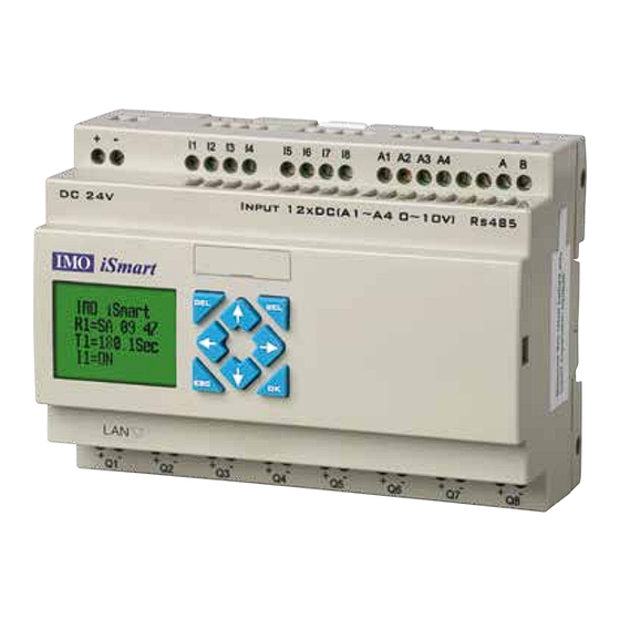
- Page 1 Instruction Manual IMO iSmart v4 Series Programmable Relay IMO Precision Controls Ltd. iSMARTv4-MANUAL...
- Page 2 Table of Contents Summary of Changes......................................Chapter 1: Getting Started....................................Quick Start Set-Up......................................Install iSmart Client Software................................Connect Power to iSmart Relay................................ Connect Porgramming Cable................................Network Connection Setup................................Establish Connection..................................p.10 Write a Simple Program..................................p.11 Chapter 2: Installation......................................p.13 Product Specification......................................
- Page 3 PWM Output Instructions....................................p.69 IO Link/Remote I/O Instructions..................................p.71 MU (Modbus)........................................p.73 SHIFT (Shift Output)......................................p.77 AQ (Analog Output)......................................p.78 AS (Add-Subtract)......................................p.79 MD (MUL-DIV)........................................p.80 PID (Proporation- Integral- Differential)................................p.80 MX (Mulitplexer)........................................ p.81 AR (Analog-Ramp)......................................p.82 DR (Data Register)......................................p.84 Chapter 6: FBD Block Diagram Programming................................ p.86 FBD Instructions........................................
- Page 4 PC Client Link Setup......................................p.158 Network Inputs & Outputs Function Setting & Application........................... p.158 Web Server........................................p.160...
-
Page 6: Summary Of Changes
Summary of Changes This user manual is modified by firmware V4.0 and SMT Client programming software V4.0. SMT V4.0 adds some new functions with the firmware to strong SMT function. The upgrade content is shown as the 2 tables below simply. More information about idiographic function to see function instruction. Edit & Display SMT V3 SMT V4 Ladder 300 Lines 600 Lines 260 Blocks 500 Blocks 4 Lines x 16 Characters 4 Lines x 16 Characters Contact &... -
Page 7: Chapter 1: Getting Started
• Check to see whether any damage occurred to the iSmart during shipment. Do not connect the iSmart relay to thepower supply if there is any sign of damage. Contact IMO Precision Controls Ltd if you find any abnormal conditions as mentioned above. Environmental Precautions The installation site of the ISmart relay is very important. - Page 8 • Prevent foreign dust, flecks, or metal scraps from contacting the iSmart relay • Avoid electric-magnetic interference (soldering or power machinery) • Avoid excessive vibration; if vibration cannot be avoided, an anti-rattle mounting device should be installed to reduce vibration Disclaimer We have reviewed the contents of this publication to ensure consistency with the hardware and software described. Since variance cannot be precluded entirely, we cannot guarantee full consistency.
-
Page 9: Quick Start Setup
Quick Start Setup This section is a simple guide for connecting, programming and operating your new iSmart relay. This is not intended to be the complete instructions for programming and installation of your system. Refer to other sections in the manual for more detailed information. Install iSmart Client Software Install the ISMART Client Software from CD or from the free internet download at www.imopc.com Connect Power to iSmart Relay... -
Page 10: Network Connection Setup
Network Connection Setup iSmart IP Address Setup - when iSmart is set to Slave >IP ADDRESS SUBNET MASK GATEWAY MASTER IP Please set IP address, subnet mask, gateway address and master IP, then click “OK” to set up iSmart network connection. Example: To edit IP address, click “OK”... -
Page 11: Establish Connection
Establish Connection 1. Open the iSmart Client software and select “New LAD” as shown below left. 2. Select “Operation/Link Com Port…” as shown below right. 3. Select he correct Com Port number where the programming cable is connected to the computer then press the “link” button. 4. The iSmart Client will then begin to detect the connected iSmart Relay to complete the connection. - Page 12 Write a Simple Program 1. Write a simple one rung program by clicking on the leftmost cell at line 001 of the programming grid, then click on the “M” contact icon on the ladder toolbar, as shown below. Select M01 and press the OK button. See “Chapter 4: Ladder Programming instructions” for complete instruction set definitions. NOTE: If the ladder toolbar is not visible at the bottom of the screen, select View/ Ladder Toolbar from the...
- Page 13 4. Select the RUN icon from the toolbar, and select “No” when the pop-up message asks “Do you want to read program from module?”, as shown below. 5. On the Input Status dialog, click on M01 to activate the contact M01 which will turn ON the Output Q01 as shown below. The highlighted circuit shows the active part, and the first Output (Q01) on the connected smart relay will be ON. See “Chapter 3: Programming Tools” for more detailed software information.
-
Page 14: General Specifications
Chapter 2: Installation General Specifications iSmart is a miniature smart Relay with a maximum of 44 I/O points and can be programmed in Relay Ladder Logic or FBD (Function Block Diagram) program. The iSmart can expand to its maximum I/O count by adding 3 groups of 4-input and 4-output modules. Power Supply Digital Inputs Input Power Voltage Range DC Models: 12-28.8V Current Consumption 3.2mA @DC; AC Models: 85-265V 1.3mA @100-240VAC; 24V AC Models: 20.4-28.8V 3.3mA@24VAC Power Consumption 24VDC: 12-point: 125mA Input Signal “OFF” Threshold DC: < 5VDC; 20-point: 185mA 100-240VAC : < 40VAC 100-240VAC: 100mA 24VAC: <6VAC... -
Page 15: Product Specifications
Product Specifications Part Number Power Digital In Digital Out Analogue In Analogue Out Comments SMT4-EA-R10 100-240VAC 6 AC 4 (8A Rly) SMT4-EA-R20 100-240VAC 12 AC 8 (8A Rly) SMT4-ED-R12 24VDC 8 DC* 4 (8A Rly) 2 (0-10V) 2 High Speed Inputs (up to 1kHz) SMT4-ED-R20 24VDC 12 DC*... -
Page 16: Direct Mounting
Mounting DIN Rail Mounting The iSmart relay should always be mounted vertically. Press the slots on the back of the iSmart and expansion module plug CONNECTOR onto the rail until the plastic clamps hold the rails in place. Then connect the expansion module and CONNECTOR with the Master (press the PRESS-BUTTON simultaneously) It is recommended to apply a DIN-rail end clamp to hold the iSmart in place. - Page 17 Input 12/24V DC Input 100~240V/24V AC Sensor Connection Output (Relay)
- Page 18 Output (Transistor) IO Link or Remote I/O Link The power supply and the I/O supply should share the same power source. Only short circuit the first and the last module. When I/O link, the net can connect 8 products in max. (ID: 0-7). When Remote I/O is available, it only can connect 2 products max (Master & Slave). More information about RS485 Model communication to see “Chapter 7 20 Points RS485 type Models Instruction”. 1A quick-blowing fuse, circuit-breaker or circuit protector Surge absorber (43V DC) Surge absorber (Input 24VAC:43V; Input 100~240VAC:430V AC) Fuse, circuit-breaker or circuit protector...
-
Page 19: Chapter 3: Program Tools
Chapter 3: Program Tools PC Programming Software “SMT Client” The SMT Client programming software provides two edit modes, Ladder Logic and Function Block Diagram (FBD). The SMT Client software includes the following features: 1. Easy and convenient program creation and editing. 2. - Page 20 Menus, Icons and Status Bar The Ladder programming environment includes the following Menus, Icons and Status Displays 1. Menu bar – Five menu selections for program development and retrieval, editing, communication to connected controllers, configuration of special functions and viewing preference selections. 2. Main Toolbar – (From Left to Right) Icons for create a new program, open a program, save a program and print a program. Icons for Keypad, Ladder view, HMI/Text edit and Symbol (comments) edit.
-
Page 21: Simulation Mode
The “A” and “L” keys or icons are used to complete parallel and serial circuits. The right column is for output coils. Simulation Mode The SMT Client software includes a built-in simulator to test and debug programs easily without the need for downloading to a controller. To activate simulation mode, simply press the RUN icon. The program below is shown in simulation mode, identifying the significant available features. -
Page 22: Establish Communication
Establish Communication The following is the simple procedure for establishing communication between PC and the iSmart smart relay. a. Select “Operation/Link…” as shown below. b. Select the correct IP address where the programming cable is connected to the computer then press the “link” button. c. -
Page 23: Online Monitoring/Editing
Online Monitoring/Editing The SMT Client software allows for online monitoring of the currently running program during runtime. Additional online functions include, I/O forcing, and Mode changes (Run/Stop/Quit). The SMT Client software does not support runtime logic editing changes. All logic edits to contacts, coils, Timers/Counters, and circuit connecting lines must be written to the connected smart relay while in Stop mode. - Page 24 HMI/TEXT This function block can display information on 16×4 LCD screen: 1. Preset value or current value of function blocks, such as Counter, Timer, RTC, Analog comparator and DR register etc. Under running mode, to modify the preset value via HMI is available. 2. Coils status, such as input coils I, Z, X and auxiliary coils M. Under running mode, to modify the M status via HMI is available. 3.
- Page 25 HMI/TEXT Setting (Steps 1-7) Enter H01 coil Into HMI/TEXT edit frame Select “T” Select “E” Select T01 current Select T01 current (unit) Choice T01 present (unit), user can modify T01 preset value when H coil enable and display on LCD. Download to iSmart, and I01 turn ON, or press “SEL” if the H coils is set to mode 1, then the iSmart LCD will display the first H text as shown below.
- Page 26 Built-in ASCII code and multi-language characters: Multi-language characters including English, French, Spanish, Italian, German, Portuguese, Polish; Also, according to the different settings, you can display Russian or Turkish characters. 85 Built-in Chinese characters, which read as following left of the HMI/TEXT editor window; 60 characters which user define, edit step 1~6 as follows right of the HMI/TEXT editor window. Setting telephone number (GSM module SMS function): Build-in 20 HMI (H01~H14) can be set telephone number for SMS alarm. When HMI which set telephone is enabled, iSmart save text information. Extension GSM module send this HMI text to telephone after reading this HMI text.
-
Page 27: Program Documentation
Stop Display Run Display Example: 1, iSmart saved H01 display information (M01 status and A01 value) when M01 is enabled rising edge. 2, Extension GSM module send SMS to telephone (H01 line1 number) after reading message (H01 line2~line4 text information). Example: HMI/TEXT and Z keypad input function Press “SEL”... - Page 28 Line Comments The Line Comment editor is accessed by clicking the “W” icon on the Ladder Toolbar. After clicking on the “W” icon, to drag the line number you want to comment and release, and then type the desired comments and press OK Analog Output Set…...
- Page 29 3-Contact/5-Contact There are 3-contact and 5-contact edit modes available in iSmart LADDER mode. In 3-Contact mode, there are three inputs and one output available in one ladder line. And the maximum line number is 600. In 5-Contact mode, there are five inputs and one output available in one ladder line In 3-Contact mode, if the ladder line is more than 200, the mode cannot change to 5-Row. In 5-Contact mode, if the input coil number is more than three, the mode cannot change to 3-Ros.
- Page 30 Data Register Set… The content of Data Register is either unsigned or signed, it can be set as shown below. Selecting Unsigned, the range of DR is 0~65535; and selecting Signed, the range of DR is -32768~32767. After the operating above, the Data Register editing environment can be access through the menu using the Edit>> Data Register Set… selection shown below.
- Page 31 Special DR Register Function If the special DR coil, DR65~DRF0, is used as a special register, it does not need to be enabled; it works as common register (its current value will equal to the pre-set value) once it is enabled. The DR65~DRF0 can retain the current value when stop or power down.
-
Page 32: View Menu
View menu The view menu includes software display option selection. The following explains the details of each function. Function Description Display usage list Display function block and parameter Display capacity left space Monitoring or Simulation coil status (I, X, Z, M, N) Simulation IO Link W status(only RS485 type) Monitoring or Simulation analog input A01~A04(only DC type) Monitoring or Simulation expand analog input A05~A08... -
Page 33: Fbd Programming Environment
FBD Programming Environment The FBD Programming Environment includes all the functions for programming and testing the iSmart using the FBD programming language. To begin a new program, select File-->New, and select the desired model of iSmart, as shown right. FBD programming operation is same as Ladder. Menu, Icons and Status Bar FBD environment include menu, icon and status bar refer to below figure. - Page 34 Simulation Mode SMT Client build-in simulation test function, the following diagram shows the display characteristics in simulation mode. Online Monitoring/Editing...
-
Page 35: Symbol And Parameters List
Symbol and Parameters list FBD list symbols for coils and function blocks which only been used in program and will comment tags appear in the program. Symbol also can describe the function of main program. The following diagram operation, click the toolbar “Comments”, Comments configuration dialog box appears, edit and click “OK”, notes will be displayed in the programming interface, and can be moved by dragging the mouse position. Parameters List: Parameters list display coils and functional blocks which used in program and explain coil functions and tags, function block settings and markings and other information, as shown below. -
Page 36: Original Screen
LCD Display and Keypad Keypad Most iSmart CPU units include the built-in LCD Display and Keypad. The keypad and display are most often used for changing timer/counter set points, controller mode changes (Run/Stop), uploading/downloading to the PM05 memory cartridge, and updating the RTC (Real Time Clock/Calendar). Although, logic programming can be performed from the keypad and display, it is highly recommended to only perform logic changes using the SMT Client software. - Page 37 Analog input A01~A04: 0~9.99V Expansion Analog input A05~A08: 0~9.99V or 0~20.00mA Expansion temperature analog input AT01~AT04: -100.0~600.0 Cent degree or -148.0~1112.0 Fahrenheit degree Expansion analog output AQ01~AQ04: 0~10.00V or 0~20.00mA • Setting voltage mode or current mode, more information to see: Chapter 4: Relay Ladder Logic Programming-AQ(Analog Output). Hidden I/O interface function: iSmart can display the states for 14 sorts of coil, as shown in below table. Each bit of DRD8 current value (except bit 14 and 15) determines the corresponding IO interface to be displayed or not. When one bit equal 1, the corresponding I/O interface is hidden (mean you cannot display the I/O interface by pressing SEL+...
- Page 38 e.g., In order to hide some, I/O interfaces. You can set DRD8 current value through running a Ladder/FBD program, you also can set it by PC-LINK as shown below: 1. Open “Edit>I/O Display Set…”: 2. Setting “I/O Display Set” as the picture shown below, and click OK 3.
- Page 39 LCD Display Main Menu (1) The Main Menu as iSmart under ‘STOP’ Mode. Press “ESC” key on keypad after power on for entering into the Ladder main menu or FBD main menu, which depends on the program format, Ladder or FBD mode in iSmart. Menu Ladder > LADDER Ladder edit LADDER FUN.BLOCK...
- Page 40 Main Menu Ladder Press the button Button Description 1. Ixx ð ixx ð - ð space ð Ixx (only for digital and character position of 1, 3, 5 column) 2. Qxx ð space ð Qxx (only for digital and character position of 8 column) ð...
- Page 41 Function PI and AR, more key display: PARAMETER Under Ladder mode into PARAMETER, press “SEL” key, cursor will into edit mode. This time if press “SEL” key continuously. Function blocks display in sequence: TŽCŽRŽGŽASŽMDŽPIŽMXŽARŽMUŽT… This time if cursor flicker on “T”, press “ / ”. Function blocks display in sequence: T1 C1 R1 G1 AS1 MD1 PI1 MX1 AR1 MU1 T… Function PI and AR, more key display: Under FBD mode, Press “SEL”...
- Page 42 Ž Move the cursor Ensure the dit Enter Edit (edit DR display number or DR preset value) ‘SEL’ then ‘SEL’ Edit DR preset value type 1. Edit DR display number (only first line) ‘SEL’ then ‘‘ 2. Edit DR preset value 1. Cancel edit 2. Back to main menu (save DR preset data) SEL+ /...
- Page 43 When IO LINK is selected, ID setting range is 0~7, which should be continuous. ID=0 default as Master, ID=1~7 default as Slave. When REMOTE I/O is selected, the distribution of the remote I/O is as follows: Master Slave Remote Input X01~X0C ...
- Page 44 Edit rule: M: Month range 1~12; ‚D: Week range 0~5, means the 0 to 5th Sunday of the setting month and 0 said the last Sunday of the setting month; ƒH: Hour range 1~22; summer hour and winter hour are the same. (2) Keypad Example: Year 2009, SUM M: 05 D: 01 Ž...
- Page 45 A Class: Password number is set to 0001~9FFF. B Class: Password number is set to A000~FFFE. Password number = 0000 or FFFF is disabled Password function, Default setting: 0000. If there are H coils(HMI coils) enable, A/B Class password have same access right; If there are no H coils enable, A/B password have different access right. A/B Class password Description: No H coil ON H coil ON Menu A Class B Class...
- Page 46 iSmart system error After power on, iSmart keep detecting the running state. Once system error occurred, the error code will display on LCD. At the same time, iSmart will stop or just give error-warning base on the error type. Error types are show in the table below: Error code Explain Error action...
-
Page 47: Chapter 4: Parameter Passing
Chapter 4: Parameter Passing In the iSmart, almost all the function block can use other function block’s current value as its preset value. This process we called data transmission. This chapter will describe some regulation about data transmission. iSmart Inner Data Type All the data stored in SMT inner system are integer. Even through some parameter likes “A01 = 9.99V” display in LED, in fact “9.99” stored in SMT inner system is “999”. Only in display stage, the decimal point of “9.99” added according to its physical significance. When analog variable and other function block current value passed to other function block or analog output as preset value, essentially just integers passed. -
Page 48: Passing Parameter Out Of Range
Passing parameter out of range MD current value data range is -32768~32767, T preset value data range is 0~9999. If MD current value is passed to T as preset value, obviously sometimes MD current may greater T preset value upper limit, or less than T preset value down limit. This moment SMT will use upper limit or down limit value as its preset value. -
Page 49: Chapter 5: Relay Ladder Logic Programming
Chapter 5: Relay Ladder Logic Programming Basic Elements General RESET PULSE N.O. N.C. Number output output output output contact contact Symbol Ù Ú (N.O./N.C.) Digital Input 12(I01-I0C/i01-i0C) Keypad Input 4(Z01-Z04/z01-z04) Digital Output 8(Q01-Q08/q01-q08) Auxiliary Coil 127(M01-M7F/m01-m7F) Auxiliary Coil 127 (N01-N7F/n01-n7F) Counter 31(C01-C1F/c01-c1F) Timer... - Page 50 Special Auxiliary Relays: M31~M3F Code Signification Description User program upstart flag Outputting ON during the first scanning period; and used as normal auxiliary relay at other scan period. 1second blinking output 0.5s ON, 0.5s OFF Summer/Winter output Summertime turn ON, winter time turn OFF, used as normal auxiliary relay. AT01 flag Output ON when the first channel of SMT-4PT error is AT02 flag Output ON when the second channel of SMT-4PT is error AT03 flag Output ON when the third channel of SMT-4PT is error AT04 flag Output ON when the fourth channel of SMT-4PT is error RS485 received flag Output ON when the RS485 port has received data. RS232 received flag Output ON when the RS232 port has received data.
-
Page 51: Output Instructions
Positive Edge Trigger - Pulse Output ( D ) A positive edge trigger (D) holds its status ON for one CPU scan time when the preceding series contact changes its state from OFF to ON. The transition from OFF to ON is called the “Positive Edge Trigger”. Negative Edge Trigger - Pulse Output ( d ) A negative edge trigger (d) holds its status ON for one CPU scan time when the preceding series contact changes its state from ON to OFF. -
Page 52: Timer Instruction
Timer Instruction The iSmart includes 31 Timer coils that can be used throughout a program. T0E and T0F keep their current value after power lost if “M Keep” is active, but the other Timers’ current value is non-retentive. Each Timer has a choice of 8 operation modes, 1 for a pulse Timer and 7 for general purpose Timer. Additionally, each Timer has 6 parameters for proper configuration. The table below describes each configuration parameter and lists each compatible element for configuring Timers. - Page 53 Timer Mode 2 (ON-Delay with Reset) Mode 2 Timer is an ON-Delay with reset that will time up to a fixed preset value and stop timing when the current time is equal to the pre-set value. Additionally, the Timer current value will be kept when Timer is disabled. In the example below, the Timer will stop timing when it reaches its preset value of 5 seconds.
- Page 54 Timer Mode 4 (OFF-Delay) Mode 4 Timer is an OFF-Delay with reset that will time up to a fixed preset value and stop timing when the current time is equal to the pre-set value. Additionally, the Timer current value will reset to zero when Timer is disabled. In the example below, the timer reset input is Input I01. The timer status bit T01 will turn ON only after its rung transitions from true to false.
- Page 55 Timer Mode 6 (FLASH with Reset) Mode 6 Timer is a Flash timer with reset that will time up to a fixed preset value and then change the state of its status bit. Additionally, the Timer current value will reset to zero when Timer is disabled. In the example below, the timer reset input is Input I01. Timer status bit T01will be ON immediately when its rung is true and begin its timing sequence.
- Page 56 Timer Mode 8 (second chronograph mode Timer mode 8 is stopwatch mode with reset control and pause control. When control condition from OFF to ON, The timer starts ticking; When the timer reaches the preset value, the output coil will change its state, and the current value of the timer will be displayed as the preset value, and the timing will not continue. When the reset control is effective, the current value of the timer and the output coil will be reset to 0.
- Page 57 Counter Instructions The iSmart includes 31 counters that can be used throughout a program. Each counter has a choice of 9 operation modes, 1 for pulse counter, 6 for general purpose counting and 2 for high speed counting. Additionally, each counter has 6 parameters for proper configuration. The tables below describe each configuration parameter and lists each compatible memory type for configuring counters.
- Page 58 Counter Mode 2 (Overtaking, Non-Retentive) Mode 4 Timer is an OFF-Delay with reset that will time up to a fixed preset Mode 2 Counter will count up to a fixed preset value and continue counting even reach the preset value, but it will not count when the current value equals 0 in counting-down mode. Additionally, the current count value is non-retentive and will reset to init value on a powering up to the smart relay or switching between RUN and STOP.
- Page 59 Counter Mode 5 (Overtaking, Up-Down Count, Non-Retentive) Mode 5 Counter’s operation is similar to Mode 2, overtaking and non-retentive. Its status bit will be ON when the counter current value is not less than its preset value and will be OFF when the current value is less than its preset value. The Mode 5 Counter will count up to a fixed preset value and continue counting even reach the preset value.
- Page 60 High Speed Counters (DC Version Only) The DC powered version smart relays include two 1 KHz high speed inputs on terminal I01 and I02. These can be used as general purpose DC inputs or can be wired to a high speed input device (encoder, etc.) when configured for high speed counting. High Speed Counter Mode 7 (DC powered versions only) Symbol Description ...
- Page 61 High Speed Counter Mode 8 (DC powered versions only) The Mode 8 High Speed Counter can use either input terminals I01 or I02 Symbol Description for forward up-counting to 1 KHz maximum at 24VDC high speed input Counting Mode (8) high speed counting signal. It will reflash its counted value in each “fixed time”. When the ‚ High speed counting input terminal: I01 or I02 only counted value reaches or excesses the “Preset ON”, then the selected counter coil turns ON at the next cycle.
- Page 62 Real Time Clock (RTC) Instructions The iSmart smart relay includes 31 RTC coils that can be used throughout a program. Each RTC instruction has a choice of 5 operation modes and has 10 parameters for proper configuration. The initial clock/calendar setting for each connected iSmart is set using the Operation» RTC Set menu selection from the SMT Client software. Symbol Description ...
- Page 63 RTC Mode 1 (Daily) The Daily Mode 1 allows the RTC coil acting based on a fixed time across a defined set of days per week. The configuration dialog below (example 1) allows setting the workdays per week (i.e., Mon-Fri) and the work hours per day. RTC coil/contact turns on in the work-hour of the workday. Example 1: Example 2: Example 3: Example 4: Example 5: Example 6:...
- Page 64 RTC Mode 2 (Interval weekly) The Interval Time Mode 2 allows the RTC coil acting based on time and day per week. The configuration dialog below (example 1) allows setting the start-working time and stop-working time between two days in each week. Example 1: Example 2: Example 3: Example 4: RTC Mode 3 (Year-Month-Day) The Year-Month-Day Mode 3 allows the RTC coil acting based on Year, Month, and Date. The configuration dialog below (example 1) allows setting the workday between two different dates.
- Page 65 Example 1: Example 2: Example 3: Example 4: RTC Mode 4 (30-second compensator) Symbol Description The 30-second compensator, Mode 4, allows the RTC coil acting based on RTC adjustment week week, hour, minute and second. The configuration dialog below shows the ‚ RTC mode 4 setting of week, hour, minute and second for the TRC mode 4. ƒ RTC present hour „ RTC present minute … RTC adjustment hour † RTC adjustment minute ‡ RTC adjustment second ˆ...
- Page 66 Example 1: preset second < 30s • The current time will return to 8:00:00 when it achieves 8:00:20 at first time, and RTC contact, R01, will turn ON, then it does not turn OFF until the present time achieves 8:00:20 again. Then time keeps going. So, this means that RTC status bit is ON for 21 seconds. Example 2: preset second >= 30s • The present time will change to be 8:01:00 when it achieves 8:00:40, and RTC status bit R01 turns ON in one scan time. Then time keeps going and R01 turns OFF. RTC Mode 5 (Astronomical Clock) Symbol Description RTC mode 5 is “Astronomical Clock Mode”, which uses the set of longitude,...
-
Page 67: Comparator Instructions
Comparator Instructions The iSmart smart relay includes 31 comparator coils that can be used throughout a program. Each comparator has 8 different operation modes. Additionally, each comparator has 5 parameters for proper configuration. The table below describes each configured parameter and lists each compatible element for configuring Comparators. Symbol Description Comparison Mode (0~7) ‚ Ax analog input value (0.00~99.99) ƒ Ay analog input value (0.00~99.99) „ Reference comparative value, could be constant, or other data code … Output terminal (G01~G1F) • The preset value ‚, ƒ and „ can be a constant or refer to other function current value. Comparator Mode 0 (Internal Coil) Mode 0 Comparator (Internal Coil) used as internal auxiliary coils. -
Page 68: Hmi Display Instructions
Example 2: Timer/Counter present value Compare The Comparator instruction can be used to compare Timer, Counter, or other function values to a constant value or each other. In this example below, Mode 5 is the selected function that compares the value of Counter (C01) with the value of Timer (T01). Status coil G01 turns ON if present value of C01 isn’t less than present value of T01. HMI Display Instructions The iSmart smart relay includes 31 HMI instructions that can be used throughout a program. Each HMI instruction can be configured to display information on the iSmart 16×4 character LCD in text, numeric, or bit format for items such as current... - Page 69 HMI function instruction 1. HMI can display character, built-in Chinese, user-defined Chinese.This information cannot be edited through keypad. 2. HMI can display function current value (T, C, R, G and DR), analog input/output value (A, AT, AQ). This information cannot be edited through keypad. 3. HMI can display preset value of function (T, C, R, G and DR). This information can be edited through keypad. 4. HMI display state of coil (I, X, Z, M and N), state of M and N can be edited through keypad.
- Page 70 Filter Function Block (Filter) iSmart includes 31 independent filter (Filter) command, 5 working mode in each comparator, please see instruction of comparators and parameters. Filter Mode 0 (Analog filter) Mode 0 Comparator (Internal Coil) used as internal auxiliary coils. No preset value. In the example below shows the relationship among the numbered block diagram for a Mode 0 Comparator, the ladder diagram view, and the software Edit Contact/Coil dialog box. Filter Mode 1 (Analog filter) Symbol Description...
- Page 71 Timing diagram (example) For example : F01 current value will update per 10s, when current value updated, F01 coil will turn ON. Filter Mode 3 (Maximum value) Symbol Description When enable coil is ON, maximum function will start, the status of output ...
- Page 72 10BPWM Output Instruction (DC Transistor Output Models Only) The transistor output model, T type, includes the capability to provide a PWM (Pulse Width Modulation) output on terminal Q01 and Q02. The PWM instruction is able to output up to an 8-stage PWM waveform. It also provides a PLSY (Pulse output) output on terminal Q01, whose pulse number and frequency can be changed.
- Page 73 Example: The preset frequency and pulse number could be constant or the current value of other function. They are variable if the preset are other data code. The PLSY will stop output if it has outputted the number of „ pulse. PLSY will run again if it is enabled for a second time. •...
- Page 74 11BIO Link/Remote I/O Instruction (SMT-CD model only) The SMT-CD models include the capability to link additional SMT-CD units via the RS-485 connection terminals. The baud rate and communication format both can be set using the Operation» Module System Set… menu selection from the SMT Client software. They also can be set through keypad like adjacent picture.
- Page 75 Example 1: IO Link Mode 1 Set = 1, ‚ = 5, ƒ = I03~I07 and ID of this unit equal to 01; the state of terminals, I03~I07, will be written into the corresponding W elements, W09~W13 as shown in the table (right). Example 2: IO Link Mode 2 Set ...
- Page 76 MU (Modbus) (Only CD type model) MU function performs Modbus RTU communication at RS485 port. There are 15 MU coils: MU01~MU0F. Remote IO and IO Link have higher priority than MU to use RS485 port. MU is executed when the remote IO setting in the system is disabled (No Remote IO) and ID is not 0. There can be several MU commands executed at the same time, but only one command can be performed, the rest are postponed until the performed one is accomplished. Function mode corresponding communication function code: The coils used for MU function: mode...
- Page 77 Setting parameter ƒ, address refers to the value of DR register: Function parameter display: Setting DR03=0001 for the address Setting DR04=0002 for the data length (means how many data will be read) The sending out Modbus command will be: 01 03 00 01 00 02 CRC16; Received response from slaver: 01 03 04 data1-1 data1-2 data2-1 data2-2 CRC16;...
- Page 78 MU mode3: Write Multiple Registers Set parameter ƒ, address, to be constant: Function parameter display: Set a constant address, 0003. Data length is fixed at 1word, means writing single register. Set data DRE0=1234 (hex: 04D2) as the content which would be written into other register. When enable the MU function, the sending out Modbus command will be 01 10 00 03 00 01 02 04 D2 CRC16; Received response from slaver: 01 10 00 03 00 01 CRC16;...
- Page 79 Set parameter ƒ, address refers to data register DR: Function parameter display: Set DR03=0001 for address Set DR04=0015 (hex: 000F) for data length; (means how many coil’s state will be read) When enable the MU function, the sending out Modbus command will be: 01 01 00 01 00 0F CRC16; Received response from slaver: 01 01 02 data1-1 data1-2 CRC16;...
-
Page 80: Shift (Shift Output)
Example: MU sending and receiving data via RS485 port when it is enabled. Here recommends user to put the D-trigger element in front of the MU coil. MU01 and MU05 coils are controlled by T01 as shown in above figure. Set MU01 as mode1, read registers mode, address starts from DR11=14=0x0E, data length DR12=4, and saving data to the registers from DR01 to DR04. Setting MU05 as mode3, write multiple registers mode, address DR13=14=0x0E, data length DR14=4, and the data which want to write into target registers refer to the value of the register, from DR05 to DR08 (DR05=10000=0x2710, DR06=8000=0x1F40, DR07=6000=0x1770, DR08=4000=0x0FA0);... - Page 81 AQ (Analog Output) The AQ instructions must be used with extension analog out module, 2AO.The default output signal of AQ is 0~10V, the AQ value and the corresponding 12 bits data value are in the range of 0~1000 and 0~4095. It also can be assigned to output 0~20mA, in current mode; the AQ value and the corresponding 12 bits data value are within the range of 0~500 and 0~2047. The 12bits data saved in DRD4~DRD7. The output mode of AQ is set by the current value of DRD0~DRD3 Output register Mode register Mode DRD0~DRD3 data definition Channel 1: AQ01 DRD4 DRD0...
- Page 82 Then enable the M01, the DRD4 output value is depending on the value of V01, changing the value of V01 also influences the output value of AQ01 and DRD4. Example 2: AQ01 preset value refers to other parameters, and the preset value of DRD4 refers to V01. Run the program, the current/output value of DRD4 will not be affected by V01 even the M01 turns ON, it only depends on the A01 (AQ01 * 4.095=DRD4). AS (Add-Subtract) Symbol Description The iSmart smart relay includes 31AS coils that can be used throughout AS current value ( -32768~32767) a program. The AS function performs a simple integral-math- ‚ V1 parameter ( -32768~32767) calculation: Addition and Subtraction. There are 6 parameters for proper ƒ...
-
Page 83: Symbol Description
MD (MUL-DIV) Symbol Description The iSmart smart relay includes 31MD coils that can be used throughout MD current value ( -32768~32767) a program. The MD function performs a simple integral-math- ‚ V1 parameter ( -32768~32767) calculation, Multiplication and Division. There are 6 parameters for ƒ... - Page 84 MX (Multiplexer) Symbol Description The iSmart smart relay includes 15 MX coils that can be used V0 parameter ( -32768~32767) throughout a program. This function set its current value to be 0 or ‚ V1 parameter ( -32768~32767) one of 4 preset values which depends on the state of selection bit 1 ƒ...
- Page 85 AR (Analog-Ramp) The iSmart smart relay includes 15 AR coils that can be used throughout a program. Each AR coils has 2 modes. AR mode 1 Symbol Description In mode1, AR current level is changed to either Level 1 or Level 2 according to the ON/OFF state of ...
- Page 86 AR mode 2 Symbol Description In mode 2, it supports four different preset levels, but only one of these 4 preset levels can be AR current value:0~32767 target level at one time. The current level will change to target level at a designed rate. There are 12 ‚ Level0:0~32767 parameters for proper configuration. The table below describes each configuration parameter and ƒ Level1:0~32767 lists each compatible element for configuring AR mode2. „ Level2:0~32767 … Level3:0~32767 †...
- Page 87 DR (Data register) he iSmart smart relay includes 240 DR coils that can be used Symbol Description throughout a program. The DR function plays an important Current value Unsigned: 0~65535 role in data-transmission. Its current value equals to preset Signed: -32768~32767 ‚ Preset value value once it’s enabled. The data can be signed or unsigned ƒ DR code (DR01~DRF0) by Operation>>module system set…menu selection from the SMT Client software or keypad set.
- Page 88 DRD0 ~ DRE3 as special registers used to set parameters, the output value function is as follows: Function Description DRD0 AQ01 output mode 0, voltage mode and reset value when stop; DRD1 AQ02 output mode 1, current mode and reset value when stop; DRD2 AQ03 output mode 2, voltage mode and keep value when stop;...
-
Page 89: Fbd Instructions
Chapter 6: FBD Block Diagram Programming FBD Instructions Input Output Coil Range Input 12 (I01~I0C) Keypad input 4 (Z01~Z04) Expansion input 12 (X01~X0C) Output 8 (Q01~Q08) Expansion output 12 (Y01~Y0C) Auxiliary coil 63(M01~M3F) Auxiliary coil 63(N01~N3F) 31 (H01~H1F) 2 (P01~P02) SHIFT 1 (S01) I/O LINK 8 (L01~L08) - Page 90 Each function block occupied a BLOCK; the available number is limited by the number of B, system memory space and function block number. Block System Function Block Number Number Memory (byte) Total source 10000 Timer mode 0 Timer mode1~6 Timer mode 7 Counter mode 0 Counter mode 1~7 Counter mode 8...
-
Page 91: Analog Input
Number Function / Logic Memory bytes Function number B Number Memory Bytes B001 Memory space limits in iSmart 10000 B002 Timer mode 7 T01, T02 Resource used by program B003 Counter mode 1 Still available in iSmart 9945 B004 B005 MD01 B006 DR register... -
Page 92: Coil Block Instruction
Example 1: AQ01 preset value is constant; When running and disable M01, DRD4 output value is AQ01 setting value 4000, and AQ01 output 9.77V; When running and enable M01, adjust the value of DRD4, AQ01 output value changed with DRD4; Example 2: AQ01 preset value is other parameters; When running, DRD4 output value is out control of I01. AQ01 output value is A01, adjust the value of A01, DRD4 output value changed with A01; Coil Block Instruction Output coils including Q, Y, M, N, H, L, P, S. FBD menu display: H, L, P, S is special function coil, and press “OK” button into function display. Press the button: Into function display when cursor address is output coil and coil type is H, L, P, S Ž... - Page 93 The iSmart smart relay includes a total of 31 HMI instructions that can be used throughout a program. Each HMI instruction can be configured to display information on the iSmart 16×4 character LCD in text, numeric, or bit format for items such as current value and preset value for functions, Input/Output bit status, and text. There are three kinds of text in HMI. They are Multi Language, Chinese (fixed) and Chinese (edit). • Only the coils, function blocks and analog value which used in the program can be set in HMI to display status, preset value and current value. Each HMI instruction has a choice of 2 operation modes. Mode1, display mode when pressing key “SEL”...
-
Page 94: Pwm Function Block (Only Transistor Output Version)
PWM function block (only transistor output version) The transistor output model smart relay includes the capability to provide a PWM (Pulse Width Modulation) output on terminal Q01 and Q02. The PWM instruction is able to output up to an 8-stage PWM waveform. It also provides a PLSY (Pulse output) output on terminal Q01, whose pulse number and frequency can be changed. - Page 95 Mode2 PLSY The PLSY output terminal Q01 can output preset number of pulse whose frequency is variable from 1 to 1000 Hz. FBD output coil display Press “OK” button into function Press “SEL” , “” and “OK” to select M01: enable input coil display stage and edit preset value •...
- Page 96 There are 10 parameters in PWM mode, please see below table : Symbol Description Enable Output PWM Mode 3 ‚ Current Value Output (1~8) Set 1 ƒ Input SelectionS1 (I01~g1F) Set 2 „ Input SelectionS2 (I01~g1F) Set 3 … Input SelectionS3 (I01~g1F) Set 4 †...
- Page 97 Click “SEL” to select preset Coil output display in FBD mode Click “OK” to enter function display value. The preset of PLSY output frequency and number of outputs could be a constant, and other encoder code either. PLSY will stop output once the number of output pulse reaches setting value.
-
Page 98: Io Link Function Block
IO Link function block Up to 8 additional iSmart units can be configured as independent Slave nodes, each running their own logic program and their I/O linked to one Master smart relay. The Master iSmart smart relay’s ID must be 00, and Slave nodes’ ID should start with 01 and be continuous. If nodes’ ID is not continuous, the Master will not communicate with those nodes which are behind the first broken. For example, the nodes’ ID is 01, 02, 04 and 05. The Master thinks there are only two Slave nodes whose ID is 01 and 02, and communication with them. Each controller can use 8 IO Link (L01~L08). Only one IO Link instruction can work at Mode 1(Send mode), and the other IO Link instructions must be Mode 2 (Receive mode). -
Page 99: Shift Function Block
Example 2: IO Link Mode 2 Set mode=2, num=5, set type of points as start from M03, set W table as from W17, when enabling the IO Link, the state “ON/OFF” of M03~M07 is controlled by the state of memory list position W17~W21. IO Link diagram as below: •... -
Page 100: Logic Block Instructions
Display Description Shift output coils Range S01: Shift code (S01) Outputs Q01~Q08 I01: Enable Input (I01~ B260) Expansion outputs Y01~Y0C I02: Shift input (I01~ B260) Auxiliary coil M01~M3F Type: Shift output coils Auxiliary coil N01~N3F Num: Preset number of output pulse (1~8) Timing diagram Logic Block Instructions Logic blocks display in FBD:... -
Page 101: Nand (Edge) Logic Diagram
NAND Logic Diagram Not(I01 And I02 And I03) Note: The input terminal is NOP which is equivalent to ‘‘Hi”; The B output ON when one of the input terminals status is OFF; NAND (EDGE) Logic Diagram Not(I01 And I02 And I03) And D Note: The input terminal is NOP which is equivalent to ‘‘Hi”; If change one input terminal to OFF when all input terminals are ON, the B output ON a scan cycle time; OR Logic Diagram I01 or I02 or I03 Note: The input terminal is NOP which is equivalent to ‘‘Lo”;... -
Page 102: Pulse Logic Diagram
SR Logic Diagram Logic Table B001 holding Note: The input terminal is NOP which is equivalent to ‘‘Lo”; NOT Logic Diagram Not I01 Note: The input terminal is NOP which is equivalent to ‘‘Hi”; Pulse Logic Diagram Note: The input terminal is NOP which is equivalent to ‘‘Lo”; The B output change status when input terminal OFFŽON; BOOLEAN Logic Diagram Note: The input terminal is NOP which is equivalent to ‘‘Lo”; Desctription:... - Page 103 The relationship between input and real table is shown below. Output Real Input1 Input2 Input3 Input4 Example (edit) Table Function Block Operation rules of FBD function blocks is basically same as ladder mode. Function blocks display in FBD: If cursor address is “Par”, user can press “OK” button into parameter display and edit preset value. Press the button: Ž...
-
Page 104: Timer Function Block
Press the button: Find and display previous or next function block when cursor address is Block number; Ž Move cursor left or right when cursor address is Preset value; SEL+ Find and display previous or next function block when cursor address is Block number; SEL+ Ž... - Page 105 (2) Timer mode 1 (ON-Delay A Mode) Mode 1 Timer will time up to a fixed value and stop timing when the current time is equal to the preset value. Additionally, the Timer current value will reset to zero when Timer is disabled. (3) Timer mode 2 (ON-Delay B Mode) Mode 2 Timer is an ON-Delay with reset that will time up to a fixed preset value and stop timing when the current time is equal to the pre-set value. Additionally, the Timer current value will be kept when Timer is disabled.
- Page 106 (4) Timer mode 3 (OFF-Delay A Mode) Mode 3 Timer is an OFF-Delay with reset that will time up to a fixed preset value and stop timing when the current time is equal to the pre-set value. Additionally, the Timer current value will reset to zero when Timer is disabled. (5) Timer mode 4(OFF-Delay B Mode) Mode 4 Timer is an OFF-Delay with reset that will time up to a fixed preset value and stop timing when the current time is equal to the pre-set value. Additionally, the Timer current value will reset to zero when Timer is disabled.
- Page 107 (6) Timer mode 5(FLASH A Mode) Mode 5 Timer is a Flash timer without reset that will time up to a fixed preset value and then change the state of its status bit. Additionally, the Timer current value will reset to zero when Timer is disabled. (7) Timer mode 6(FLASH B Mode) Mode 6 Timer is a Flash timer with reset that will time up to a fixed preset value and then change the state of its status bit. Additionally, the Timer current value will reset to zero when Timer is disabled.
- Page 108 (8) Timer mode 7(FLASH C Mode) Mode 7 Timer is a Flash Timer which using two Timers in a cascade configuration without reset. The second Timer number follows the first Timer. The cascade configuration connects the timer status bit of first timer to enable the second timer. The second timer will time up to its pre-set value then flash and its timer status bit will enable the first timer. Additionally, the Timer current value will reset to zero when Timer is disabled. (9) Timer Mode 8 Timer mode 8 is including reset control and suspend control, control condition is from OFF to ON. When timer start to time until preset value, output coil will change the status, timer current value will display preset value and stop timing, when reset control is valid, the current value and output coil of timer will reset to 0.
-
Page 109: Common Counter Function Block
Common Counter function block There is a maximum of 250 counter function blocks under FBD mode, can be set mode 0~6 as common counter and mode 7~8 as high-speed counter, and the function is same as Ladder mode. Counter edit and display: (1) Counter Mode 0 (internal coil) Mode 0 counter (Internal Coil) used as internal auxiliary coils. - Page 110 • Under this mode, the counter current value will be initial value when the smart is power up or switching between RUN and STOP. The init value is 0 if the counter configured as counting up, else, it is preset value. (3) Counter Mode 2 (Continuous Count, Non-Retentive) Mode 2 Counter will count up to a fixed preset value and continue counting after the preset value, but it will not count when the current value equals 0 if it is configured as down Counter. Additionally, the current count value is non-retentive and will reset to init value on a powering up to the smart relay or switching between RUN and STOP.
- Page 111 (4) Counter Mode 3 (Fixed Count, Retentive) Mode 3 Counter operation is similar to Mode 1 except its current count value is retentive when Counter powers down. So, the current value won’t be initiate value when Counter powers up but be the value when it powering down. Mode 3 Counter will count up to a fixed preset value and stop counting at that value or stop counting when its current value is 0 if it’s configured as down counter. Note: The “PD” means the current value will be retain until the power recover; This mode is similar to mode 1, but: • First 31 Counter functions (C01~C1F) can keep their current value after a loss of power to the smart relay. •...
- Page 112 (6) Counter mode 5 (Continuous Count, Up-Down Count, Non-Retentive) Mode 5 Counter’s operation is similar to Mode 2 except its current count value is continuous and non-retentive. The status bit is fixed to the non-zero preset value regardless of the state of the direction bit. Its status bit will be ON when the counter current value is not less than its preset value and will be OFF when the current value is less than its preset value.
-
Page 113: High Speed Counter Function Block (Dc Version Only)
Note: The “C” means compare count; The “>”means the current value appeared will be greater than present value; The “PD” means the current value will be retain until the power recover; • First 31 Counter functions (C01~C1F) can keep their current value after a loss of power to the smart relay. •... - Page 114 (2) Counter Mode 8 (DC powered versions only) The Mode 8 High Speed Counter can use either input terminals I01 or I02 for forward up-counting to 1 KHz maximum at 24VDC high speed input signal. The selected Counter Coil (C01-C1F) will turn ON when the pulse count reaches the target “Preset ON” value and remain ON until the pulse count reaches the target “Preset OFF” value. The counter will reset when the preceding rung is inactive. Note: High speed input terminal I01,I02 (3) High Speed Counter Mode 8 (1KHZ AB phase Input Counter) Mode 9 is the AB phase high-speed counting function, which counts two pulses with the same periodic pulse width but a phase difference of 90°. The editing...
-
Page 115: Rtc Comparator Function Block
RTC Comparator Function Block There is a maximum of 250 RTC function blocks under FBD mode, can be set mode 0~4 and the function is same as Ladder mode. (1) RTC Mode 0(Internal Coil) Mode 0 RTC (Internal Coil) used as internal auxiliary coils. No timer preset value and no parameter display. (2) RTC Mode 1(Daily) The Daily Mode 1 allows the Rxx coil to active based on a fixed time across a defined set of days per week. The below example1 allows for selection of the number of days per week (i.e., Mon-Fri) and the Day and Time for the B002 (R01) coil to activate ON, and the Day and Time for the B002 (R01) coil to deactivate OFF. - Page 116 (3) RTC Mode 2 (Continuous) The Interval Time Mode 2 allows the Rxx coil to activate based on time and day per week. The below example1 allows for selection of Day and Time for the B002 (R01) coil to activate ON, and Day and Time for the B002 (R01) coil to deactivate OFF. Example 1: Note: Parameter display current time: week, hour and minute;...
- Page 117 Example 2: Example 2: (5) RTC Mode 4 (30-second adjustment) The 30-second adjustment Mode 4 allows the Rxx coil to activate based on week, hour, minute and second. The below examples show for selection of week, hour, minute and second for the B002 (R01) coil to activate ON, and 30-second adjustment then B002 (R01) OFF. Example 1: adjustment preset second < 30s Note: Parameter display current time: week, hour, minute and second; Parameter display adjustment preset value: week, hour, minute and second •...
-
Page 118: Analog Comparator Function Block
Example 2: adjustment preset second >= 30s • The present time will change to be 8:01:00 when it achieves 8:00:40, and RTC status bit B002 (R01) turns ON. Then time is gonging on and B002 (R01) turns OFF. This means that the RTC status bit will be ON for one pulse. (6) RTC Mode 5 (Astronomical Clock) RTC mode 5 is astronomical clock mode, using the set latitude and longitude, offset time, to control the output of the RTC coil. The following figures and tables illustrate the display form and parameter meaning of RTC mode 5 and the programming interface in FBD mode. Set E/W(east and west longitude) and longitude values as well as S/N(south and north latitude) values. - Page 119 (2) Analog Comparison Mode 1~7 Analog comparator mode 1~7, setting three parameters, analog input Ax, analog input Ay and reference value G. Analog Comparator mode 1: (Ay- reference value G)≤Ax≤(Ay+ reference value G) , output ON; Analog Comparator mode 2: Ax≤Ay, output ON; Analog Comparator mode 3: Ax≥Ay, output ON; Analog Comparator mode 4: reference value G≥Ax, output ON; Analog Comparator mode 5: reference value G≤Ax, output ON; Analog Comparator mode 6: reference value G=Ax, output ON; Analog Comparator mode 7: reference value G≠Ax, output ON; Example for program and edit: Analog Comparison Mode 1 B003 (G01) output ON when the value of A01 in between (A05-2.50) ~ (A05+2.50);...
- Page 120 Analog Comparison Mode 4 B003 (G01) output ON when the value of A01 is not greater than 2.50; Parameter display current value of Ax when running mode; Analog Comparison Mode 6 B003 (G01) output ON when the value of A01 is equal to 2.50; Parameter display current value of Ax when running mode;...
- Page 121 Software Filter Mode (Mode 1) The value will be updated by each scan cycle, it will use last 5 AD average value except maximum and minimum one. (Mode 2) The value will be updated by each 5 scan cycles, it will use 5 time mode 1 value to do average. (Mode 3) The value will be updated by each 25 scan cycles, it will use 5 time mode 2 value to do average of maximum and minimum value.
-
Page 122: As (Add-Sub) Function Block
Timing Diagram (example) Filter Mode 3 (Maximum value) When enable coil is ON, maximum function will start, the status of output coil and enable coil is same. When enable coil is OFF, maximum function will close, the status of output coil and enable coil is same. In enable coil ON status, F function block current value will save the maximum value of analog input Ax. Filter Mode 4 (Minimum value) When enable coil is ON, maximum function will start, the status of output coil and enable coil is same. -
Page 123: Md (Mul-Div) Function Block
FBD display: Parameter display: AS and V1~V3, values range from -32768~32767 MD (MUL-DIV) function block There is a maximum of 250 MD (Multiplication and Division) function blocks under FBD mode, and the function is same as Ladder mode. Compute formula: MD=V1*V2/V3 Parameters V1, V2, and V3 can be a constant or other function current value. The output coil will be set to 1 when the result is overflow or parameter V3 is zero. -
Page 124: Pid (Proportion- Integral- Differential) Function Block
PID (Proportion- Integral- Differential) function block There is a maximum of 30 PI (PID) function blocks under FBD mode, and the function is same as Ladder mode. PID computes formula: = SV - PV ∆PI = K - EV - PV - PV ∑... -
Page 125: Mx (Multiplexer) Function Block
MX (Multiplexer) function block There is a maximum of 250 MX (Multiplexer) function blocks under FBD mode, and the function is same as Ladder mode. This special function transmits 0 or one of 4 preset values to MX current value memory by selection control coils S1 and S2. The MX function enables simple operations to be carried out on integers. The preset value V1~V4 can be constant or other function current value. The table below describes the relationship between parameter and MX current value. Control Status MX Output Coil MX Output Value... -
Page 126: Ar (Analog-Ramp) Function Block
AR (Analog-Ramp) function block There is a maximum of 30 AR (analog ramp control) function blocks under FBD mode, and the function is same as Ladder mode. (1)AR mode1 AR current value: 0~32767 Function description: Level1:-10000~20000 AR will keep the current level at “StSp + Offset “B”” for 100ms when it’s enabled. Then the current level runs from StSp + Offset “B” to target level at enactment Rate. If St is set, the current level Level2:-10000~20000 decreases from current level to level StSp + B at enactment Rate. Then AR holds the level StSp + MaxL (max level):-10000~20000 Offset “B” for 100ms. After 100ms, AR current level is set to offset “B”, which makes AR current Start/Stop level (StSp): 0~20000... - Page 127 (2)AR mode2 AR current value: 0~32767 Function description: Level0: 0~32767 AR will vary from 0 to current level at a preset rate when it is enabled. Based on the state Level1: 0~32767 of Sel1 and Sel2, Current level will change to other preset level at the preset rate. When Level2: 0~32767 AR is disabled, current output vary to 0 immediately.
-
Page 128: Dr (Data-Register) Function Block
DR (Data-Register) function block There is a maximum of 240 DR (data register) function blocks under FBD mode, and the function is same as Ladder mode. The DR function is transferring data. DR sends data from prevention registers to current register and output coil Bxxx ON when it is enabled. DR holding the out value and output coil Bxxx OFF when it is disabled. The data can be signed or unsigned by Operation>>module system set…menu selection from the SMT Client software or keypad set. - Page 129 The time out time is depending on communication baud rate as shown in the table below: Baud rate (bps) Time out (ms) 4800, 9600, 19200, 38400 57600 115200 • More information about communication to see: Chapter 7 20 Points RS485 type Models Instruction. MU mode1: Read Registers Setting communication address is constant: Address is constant 0003, Data length is fixed at 1word, Send data: 01 03 00 03 00 01 CRC16;...
- Page 130 MU mode2: Write single register Setting communication address is constant: Address is constant 0003, Setting data DRE0=1234 (hex: 04D2), Send data: 01 06 00 03 04 D2 CRC16; Received response form slave1: 01 06 00 03 04 D2 CRC16; Mode 2 Setting communication address is data register DR: Setting address DR03=0001, Setting data DRE0=1234 (hex: 04D2), Send data: 01 06 00 01 04 D2 CRC16; Received response from slave1: 01 06 00 01 04 D2 CRC16;...
- Page 131 MU mode3: Write Multiple Registers Setting communication address is constant: Address is constant 0003, Data length is fixed at 1word, Setting data DRE0=1234 (hex: 04D2), Send data: 01 10 00 03 00 01 02 04 D2 CRC16; Received response from slave1: 01 10 00 03 00 01 CRC16; Mode 3 Setting communication address is data register DR: Setting address DR03=0001, Setting data length DR04=0002, Setting data DRE0=1234 (hex: 04D2), Setting data DRE1=5678 (hex: 162E),...
- Page 132 MU mode4: Read Coils Setting communication address is constant: Address is constant 32 (hex: 0020), Data length is fixed at 16 (hex: 10H, 1word), Send data: 01 01 00 20 00 10 CRC16; Received response from slave1: 01 01 02 data1 data2 CRC16; Saving data to DRE0: DRE0 = data1~2 Mode 4 Setting communication address is data register DR: Setting address DR03=0001,...
- Page 133 MU mode5: Write single coil Setting communication address is constant: Address is constant 0003, Setting data DRE0=65280 (hex: FF00), Send data: 01 05 00 03 FF 00 CRC16; Received response from slave1: 01 05 00 03 FF 00 CRC16; Mode 5 Setting communication address is data register DR: Setting address DR03=0001, Setting data DRE0=65280 (hex: FF00),...
-
Page 134: Chapter 7: Hardware Specification
Chapter 7: Hardware Specification Normal Specification Content Specification Mode of user program Ladder & FBD Operation temperature -4° to 131°F (-20° to 55°C) Storage temperature -40° to 158°F (-40° to 70°C) Environmental Maximum humidity 90% (Relative, non-condensing) Operation Gas No corrosive gases Maximum Vibration 0.075mm amplitude, 1.0g acceleration according to IEC60068-2-6 Shock Resistance peak value 15g, 11ms according to IEC60068-2-27 Contact ±4KV, air discharge ±8KV... -
Page 135: Power Specifications
Power Specifications AC Models DC Models Expansion Units 10 I/O 20 I/O 12 I/O 20 I/O Operating Temperature -20 to +55°C Storage Temperature -40 to +70°C Humidity 5 - 90% RH no frost Vibration IEC60068-2-6 (0.075mm Amplitude / 1G Acceleration) Impact Resistance IEC60068-2-28 (15g peak, 1ms duration) Installation IP20, Direct or DIN Rail Mount (TS35 - 35mm) ESD: ±4kV, Air Discharge: ±8kV, EFT: Power AC: ±2kV, AC: ±1kV, CS: 0.15-80mHz 10V/m,... -
Page 136: Power Circuitry Diagram
Power Circuitry Diagram 1) AC 10/20 points 2) DC 24V 3) Mainframe, expansion and communication Input Specifications 100~240V AC model Content SMT4-EA-R10 SMT4-BA-R10 SMT4-EA24-R20 SMT4-BA-R20 I01~I06 I01~I09, I0A, I0B, I0C Input Circuitry Number 6 (digital input) 12 (digital input) Signal current input AC 110V 0.66mA AC 220V 1.3mA AC 110V 0.55mA AC 220V 1.2mA... - Page 137 Input Specifications 24V AC model Content SMT4-EA24-R10 SMT4-EA-R20 I01~I06, I09,I0A I01~I09, I0A, I0B, I0C Input Circuitry Number 6 (digital input) 12 (digital input) Signal current input ON current input > AC 14 V /3mA > AC 14 V/ 3mA OFF current input < AC 6 V /0.85 mA < AC 6 V / 0.85mA Wire length <...
-
Page 138: Output Specifications
24V DC, 20 I/O model Content SMT4-ED-R20 & SMT4-CD-R20 & SMT4-CD-T20 Analog input used as Normal digital input High speed input Analog input normal digital input I03~I08 I01, I02 I09, I0A, I0B, I0C Input Circuitry Number Signal current input 3.1mA/24V DC 3.1mA/24V DC 0.63mA/24V <0.17 mA/10V ON current input >1.875mA/15V >1.875mA/15V... -
Page 139: Life Of Relay
Inductance Load There will be a surging voltage (KV) when the inductance load switches between ON and OFF, especially for the relay model. The methods to different power mode to absorb the surging voltage are shown below. AC power, CR absorbing DC power, flywheel diode Please do not use capacitance alone as absorbing as shown below. Life of Relay Power Mode Mode Input/Output DC +12V AC 100~240V / DC +12V DC +24V AC 100~240V / DC +24V •... - Page 140 iSmart Dimensions 10/12 points 20 points...
-
Page 141: Function Parameters
Chapter 8: 20 Points RS485 Type Models Communication Function NOTE: SMT4-CD-R20, SMT4-CD-T20 have RS485 communication function Only There are many parameters needed to be set before user uses the RS485 communication function. And there are two ways to set that parameter. Setting parameters via SMT Client software: 1. In SMT Client Soft Select Operation>>Module System Set; 2. Open the dialog box as show below, setting parameters SET ID, Remote I/O and RS485 Set. Setting parameters via keypad button on iSmart: 1. Press button to enter main menu. 2. -
Page 142: Communication Parameters
Communication parameters Content Data Meaning 8/N/2 Data 8bits, No Parity, 2 Stop bits. 8/E/1 Data 8bits, Even Parity, 1 Stop bit. Format 8/0/1 Data 8bits, Odd Parity, 1 Stop bit. 8/N/1 Data 8bits, No Parity, 1 Stop bit. 4800 bps 9600 bps 19200 bps Baud Rate 38400 bps... - Page 143 IO Link Function Function description: Up to 8 iSmart units can be linked together as the IO Link Network. Each unit runs their own logic program; the ON/OFF state of input, output points, and Auxiliary Coils in each one can be assigned to “W Table”, see the next page for more information. There must be one master (ID=00) and several slaves with the continuous ID number starting from 01 in the network. The master one does not perform the IO Link function to the units with the ID behind the first broken number once the ID numbers are not continuous. For example, the slaves’ ID are 01, 02, 04 and 05, the master just can recognize only two Slave, ID 01 and 02, the ID 04 and 05 will be skipped.
-
Page 144: Mu Instruction (Modbus Rtu Master)
3. Set L01 of the iSmart which’s ID =7 as fellow illustration. 4. L01 of other 7 iSmart set as fellow illustration. 5. Run program and let I01 of the iSmart which’s ID = 7 on. And M01~M08 will be on state. 6. You will find N01~N08 of other 7 iSmart will be controlled by the M01~M08 of the iSmart which’s ID=7. MU instruction (Modbus RTU master) MU function performs Modbus RTU communication at RS485 port. There are 15 MU coils can be used in ladder mode, MU01~MU0F, and up to 250 MU function blocks diagram in FBD mode. There can be several MU commands executed at the same time, but only one command can be performed, the rest are postponed until the performed one is accomplished. -
Page 145: Modbus Rtu Slave Function
In FBD mode, program, edit and parameter display as shown below; Mode 1 More description and examples to see Chapter6: FBD Block Diagram Programming-MU (Modbus) function block. • The max data length for Mode 1 and 3 is 25words. The max data length for Mode 4 is 400bits. Modbus RTU slave function Function description: iSmart unit can be controlled by the computer or other controller using the communication control. PC and other controller can read and write IO state, preset value of the elements and the setting of the unit. -
Page 146: Register Address
Command Format: Slave Address Function Code Data CRC-16 Exception Code 00H: broadcast to all the drivers Read coils 01H: to the No.01 driver Write single coil CRC verifying For detail, For detail please range contain 0FH: to the No.15 driver Read registers please refer refer register... -
Page 147: Chapter 9: Expansion Modules
Chapter 9: Expansion Modules Summary Digital Input/Output module:SMT-MA-R8 , SMT-MD-8 ,SMT-MD-T8 Analog Input module: SMT-4PT, SMT-4AI Analog Output module: SMT-2AO iSmart can connect with expansion module. The maximal connectible number to the expansion module is: 3 Digital IO modes, 2 Analog Output modes, 2 Analog Input modules (one 4PT and one 4AI). If the iSmart system is combined with digital IO, analog IO and communication module, it must follow the standard arrangement, “SMT + digital IO module + analog IO module ”, otherwise it cannot work correctly. -
Page 148: Installation
Mainframe + digital IO (V3.0) * 3+2AO*2+4PT*1+4AI*1 Power The input voltage, current and power consumption for each expansion module is listed as below table: Module Voltage Current Power SMT-4AI 24 Vdc 70 mA 1.68w SMT-2AO 24 Vdc 85 mA 2.04w SMT-4PT 24 Vdc 55 mA 1.32w Size... - Page 149 DANGER: HAZARDOUS VOLTAGE Cut off all power before maintenance Electric shock will result in death or serious injury.
-
Page 150: Digital Io Module
Digital IO Module The iSmart must set the number of expansion IO when connect with expansion module. The method of setting IO number is shown below. 1) Keypad 2) SMT Client Software Expansion display state Installation and Wiring Expansion module: SMT-MD-R8/T8, SMT-MA-R8/MA24-R8... - Page 151 Wiring 1. 24V DC power input 2. 24V / 100~240V AC power input 3. Relay output 4. Transistor output - 1A quick-blowing fuse, circuit-breaker or circuit protector ‚ - Surge absorber (43V DC) ƒ - Surge absorber (Input 24VAC: 43V; Input 100~240VAC: 430V AC) „ - Fuse, circuit-breaker or circuit protector … - Inductive load...
- Page 152 AC inductive load needs to connect Surge absorber in parallel way to absorb the noise if the iSmart output terminal is the relay type. DC inductive load needs parallel connect commute diode if the iSmart output terminal is the relay type. The specification of inverse voltage for commute diode should be more than 5~10 times the rated current of the circuit, and the specification of positive current of diode should be more than load current. Inductive load needs parallel connect commute diode if the iSmart output is transistor. Digital IO module and Analog module both have indicator light in orange color. The state of indicator light in different operation state is the same. The state of indicator light is shown below.
-
Page 153: Analog Module
Analog Module The maximal connectible number of Analog expansion module to SMT is 2*2AO, 1*4PT and 1*4AI. Analog Input Module 4AI The 4 channel 12bits analog input module, 4AI, has the corresponding registers, A05~A08, DREC~DREF, DRE4~DRE7. It can accept either 0~10V or 0~20mA signal, the range of the measured value is different which depends on the input signal mode. See the below table for more information. Content Standard Mode Voltage Current Analog Output Range 0V~10V 0mA~20mA Differentiation 10mV 40µA Digital Output 0.00V~9.99V 0.00mA~20.00mA A05~A08 0~999 0~500 Register DREC~DREF 0~4095 0~2047 Value DRE4~DRE7 0~2000 Definition ± 2.5% ± 2.5% The current value of 4AI input displaying as shown below: Wiring... -
Page 154: Temperature Input Module 4Pt
Temperature Input Module 4PT The 4 channel 12bits temperature (PT100) analog input module, The input value of SMT-4PT is over range if wiring error or no input, SMT 4PT, has the corresponding registers with AT01~AT04. will not update the corresponding channel, and the corresponding Error coil (M) turns ON. Content Standard Coil AT Number Temperature input range -100°C~600°C AT01 SMT-4PT channel 1 error Digital output -100.0°C~600.0°C AT02 SMT-4PT channel 2 error Differentiation 0.1°C AT03 SMT-4PT channel 3 error Definition ±1%... -
Page 155: Analog Output Module 2Ao
Analog Output Module 2AO iSmart main unit can connect with two 2-channel, 12bits analog output module, 2AO, at the same time. The close one will be auto-assign to AQ01~AQ02, and the other is distributed to AQ03~AQ04. It can out 0~10V voltage signal or 0~20mA current signal, and the data in the 12bits data register, DRD4~DRD7, will determined the output of AO channel. See the below table for more information. Content Standard Mode... - Page 156 Wiring Voltage Output Current Output Voltage Output Current Output...
-
Page 157: Chapter 10: External Memory
Chapter 10: External Memory iSmart Storage Card Instruction iSmart can use SD card as External memory for data transfer: 1. Read-write card: copy user programs (screen keys, PC upper computer, iSmart automatic operation) by reading and writing SD card. 2. Record and output data: iSmart can record some data in operation according to the user’s program and output it in a fixed format. 3. Formatting card: iSmart only supports the micro SD card in the format of FAT32 file system to store programs. If the memory card is used in other formats, please format the card into FAT32 format first. - Page 158 Data Record and Output (Log Function) 1. Edit data record Edit data record function as following photo: For example, these types can be set to target register of data record function.The value in per-set value target register could be stored in iSmart or micro SD card once M11 coil enabled.
- Page 159 Read Setup Document iSmart blind type models(B Type) can set the configuration through read XXX.ini document. XXX.ini document can be used to set iSmart configuration, it’s stored under sub-menu of SD card.(User will get “error” on display when move the document out of original location or re-write file name. When iSmart changes the status from STOP to RUN, it will read the content from setup document and re-write the data for target register. Instruction of setup document: Set Default IP ADDRESS SMT blind type models (B Type) have no keypad , iSmart Provide a way that using SD card to set Default IP ADDRESS; Open “XXX.ini” file under root directory of SD card; Edit according to these rules.
- Page 160 Chapter 11: Ethernet Function Instructions Summary iSmart series products support Ethernet communication function. Users can use the Ethernet function to achieve the following operations: • Read ,Write, and monitor user program • Expand device and configure network IO module • Network server • Device program upgrade Connect iSmart has an Ethernet connector and an Ethernet status LED.
- Page 161 PC Client link setup Connect iSmart and PC with Ethernet cable, open SMT Client and choose LADDER or FBD editing environment. Right click “station” under the project and Select the pop-up “link” option. Or click “link” under “operation” in the menu. Popup “Link Com Port”: Note: it is necessary to modify the IP address of PC and iSmart device in the same network segment.
- Page 162 Legend: The status of network digital output K01 is output to M02 of slave device 192.168.0.102. Legend: The network analog input NAI01 reads the value of C01 of the slave device 192.168.0.100. Legend: The value of network analog output NAQ01 is output to T03 of slave device 192.168.0.101. Examples in LADDER:...
- Page 163 Open the browser, enter the IP address of the iSmart device, and open the iSmart web server page. Enter the username and password (username: IMO, password: IMO), log in and get permission to view the information and working status of the device.
- Page 164 The running status information of the device: When i/o status is displayed, press the “previous page” or “next page” button to switch the display page. When setting information is displayed, the page cannot be changed, and only English and Numeric character can be displayed. SMTIP address, Subnet mask, Gateway, Remote master IP and master/slave mode: Logout:...
- Page 166 Tel: 416 639 0709 IMO South Africa Email: sales-ca@imopc.com IMO Pacific Web: www.imopc.com IMO Automation LLC IMO South Africa (Pty) Ltd IMO Pacific Pty Ltd Steeplechase Industrial Park Unit 2, Trio Park Unit 9, Dillington Pass Suite E, 5845 Steeplechase Blvd Prime Park, Printers Way Landsdale...
Need help?
Do you have a question about the iSmart v4 Series and is the answer not in the manual?
Questions and answers