Table of Contents
Advertisement
Quick Links
Advertisement
Table of Contents

Summary of Contents for PiezoMotor Microstep Driver 206
- Page 1 PiezoMotor Microstep Driver 206/236 Technical Manual...
- Page 2 Stålgatan 14, SE-754 50 Uppsala, Sweden All rights reserved, icluding those to the translation. No part of this description may be duplicated, reproduced, stored in an information system or processed or transferred in any other form without prior express written permission of PiezoMotor Uppsala AB.
-
Page 3: Table Of Contents
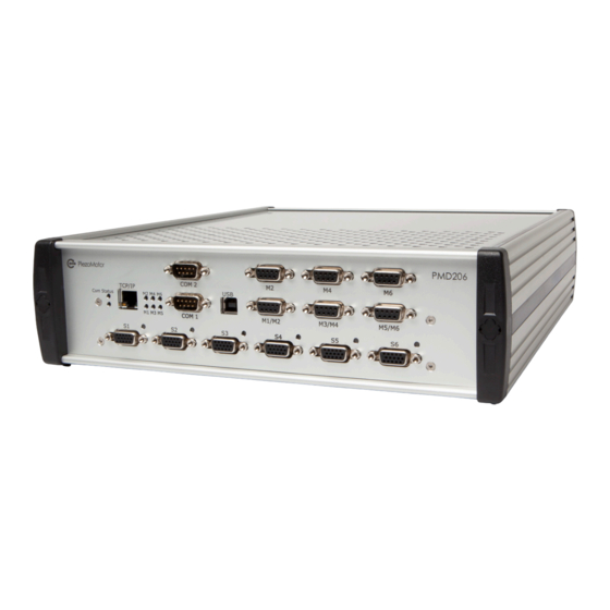
Overview This document is a guide to the technical aspects of installing and using the PiezoMotor Microstep Driver 206 and the PiezoMotor Microstep Driver 236 (hereafter referred to as PMD206 and PMD236). The PMD206 is an advanced 6-axis driver for Piezo LEGS linear and rotary motors from PiezoMotor. The PMD236 is basically six PMD206’s packaged in a rack, forming a 36-axis driver. - Page 4 5 ‒ Detailed Technical Description 6 ‒ Commands 6.1 Introduction ................................13 6.2 Power On ..................................13 6.3 Host Communication ..............................14 6.4 Basic Settings ................................15 6.5 Controller Parameter Settings ...........................16 6.6 Sensor Board Parameter Settings ..........................18 6.7 Run Commands .................................20 6.8 Controller Status ...............................22 6.9 Error Codes ................................24 6.10 Firmware Version ..............................24 7 ‒...
-
Page 5: Important Information
1 ‒ Important Information 1.1 Symbols Used in this Document Caution! This pictogram with the wording “Caution!” indicates an imminent danger which can result in slight physical injuries or material damage. ►This arrow points out the appropriate precautions. Regulation! This pictogram with the wording “Regulation!” indicates a statutory regulation, guideline or directive which must be observed in respective context of the text. -
Page 6: Safety Instructions
Note! The PMD206 / PMD236 driver is a high-end product intended for use with PiezoMotor’s Piezo LEGS product line. In order to get best performance and reliability it is important that the driver unit is handled according to the instructions given in this manual and other delivery documents. -
Page 7: Delivery
These items are included in the box at delivery: PMD206 driver unit 2 meter power cord with CEE 7/7 plug CD with PiezoMotor Motion System software and pdf-version of this document (latest version of software and manual is available on the PiezoMotor homepage) Chapter 2 ‒ Delivery... -
Page 9: Functional Principle
3.1 Piezo LEGS Linear and Rotary Motors The PMD206 / PMD236 driver unit is made to control PiezoMotor’s linear and rotary Piezo LEGS motors. The Piezo LEGS technology is characterized by its outstanding precision and high resolution. The motors are backlash free because of the friction based direct drive. -
Page 10: Piezomotor Microstepping Driver
2 kHz drive frequency is ~6 µm • 2000 Hz = ~12 mm/s. To conclude, with an unbalanced load the resulting speed will be different for forward and reverse motion. 3.3 PiezoMotor Microstepping Driver The PMD206 / PMD236 is a high resolution microstepping driver made for Piezo LEGS linear and rotary motors. -
Page 11: Quick Start
Connect to the driver unit using RS485 or TCP/IP. Connect the power cord and switch on the driver. Start PiezoMotor Motion System software and scan for driver units. Software will detect and list all connected driver units. Double click on the driver unit in the list to start wizard. The Wizard will help you configure the basic settings. -
Page 12: Installation
4.2 Installation 4.2.1 Cooling The driver unit is cooled by convection with internal fans, and therefore needs free space for this purpose. If the driver gets overheated it will automatically stop running the motor. 4.2.2 Power Supply The driver unit is powered with 90-264 V AC, 50/60 Hz. The PMD206 is fused at 5 A, and the PMD236 at 10 A. 4.2.3 Host Communication The driver unit connects to a host (e.g. - Page 13 PMD206 RS485 Host (PC) Direct (Quadrature or SSi) Sensor Switch PMD206 RS485 TCP/IP Host (PC) TCP/IP External Sensor PMD206 RS485 Host (PC) RS422 External Sensor Chapter 4 ‒ Quick Start...
- Page 14 PMD206 Switch TCP/IP TCP/IP Host (PC) Direct (Quadrature or SSi) Sensor Switch PMD206 TCP/IP TCP/IP TCP/IP Host (PC) External Sensor PMD206 Switch TCP/IP TCP/IP Host (PC) RS422 External Sensor...
-
Page 15: Detailed Technical Description
5 ‒ Detailed Technical Description Editorial note - this chapter will be included in a later revision of this document. Chapter 5 ‒ Detailed Technical Description... -
Page 17: Commands
6 ‒ Commands 6.1 Introduction Each command to the driver starts with the letters PM followed by one digit <ID>, and one digit <axis>. All commands shall end with ‘Carriage Return’ character (CR), i.e. ASCII character 13. A command time-out (300 ms) silently rejects a command and sets an internal error code. -
Page 18: Host Communication
6.3 Host Communication Communication with the driver is via serial line (4-wire RS485), or via Ethernet (TCP/IP socket). Several PMD206 units may be connected on the same RS485 line, provided that they have different identifier <ID> and that responses are allowed to finish before addressing the next module. These are the settings for serial communication: RS485 Communication Settings Baud Rate Start Bit... -
Page 19: Basic Settings
6.4 Basic Settings The basic settings defines how the driver will interact in the system. For example, you need to enable closed loop operation, and assign the sensor interface (e.g. an encoder connected to the internal sensor board, or data collection from an external sensor via RS422 or Ethernet). -
Page 20: Controller Parameter Settings
6.5 Controller Parameter Settings The PMD206 / PMD236 must be configured correctly in order to get best performance out of the Piezo LEGS motor in your application. For instance, to run in closed loop you need to have ramping parameters set according to the actual external loads in your application. - Page 21 Controller Parameter Settings <par> <value> Description Examples Notes Notes Speed ramp down in target mode - wfm-steps/second at 1 wfm-step from target Default value: 30 (U16) StepsPerCount - Target mode parameter which tells the controller how many Default value: 147b (U32) wfm-steps to run to reach target.
-
Page 22: Sensor Board Parameter Settings
6.6 Sensor Board Parameter Settings The internal sensor board can be used for quadrature encoders and SSI sensors. It also provides digital in/out of which some may be used for limit switch signal inputs. has an own set of parameters which needs to be configured if you intend to connect an encoder directly to the driver. - Page 23 Sensor Board Parameter Settings Cmd Description <par> <value> Examples Notes Notes I/O port - set command for output pins Set command: PM11SB=5,<value > PM11SB=5,1 Example: to set Out 0 high, and clear Out 1 and Out 2 value Out 2 Out 1 Out 0 I/O port - read command for status on input and output pins...
-
Page 24: Run Commands
6.7 Run Commands Run Commands Cmd Description Examples Notes A set command to park Send to axis 1: PM11CC=<value> Where <value> is: and unpark motor, PM16CC=<value> 0 to unpark motor but also to initiate Send to axis 6: 1 to park motor parameters from flash Send broadcast: PM10CC=<value>... - Page 25 Run Commands Cmd Description Examples Notes This is a set command Send to axis 1: PM11RS=<freq>,<µstep>,<dir> <freq> wfm-step frequency to run a number of [wfm-steps/second] microsteps in open Send to axis 6: PM16RS=<freq>,<µstep>,<dir> <µstep> number of microsteps loop. Send broadcast: PM10RS=<freq>,<µstep>,<dir> <dir>...
-
Page 26: Controller Status
Run Commands Cmd Description Examples Notes The data recorder Send broadcast: PM10DR=0 to enable and arm When using auto trig mode (0), will store 100 motor auto trig the unit will wait for TP, TR or position values for all PM10DR=1 to enable and RS commands before start of... - Page 27 Controller Status Status Code <ssiimm> Description S1-6 LED Command Type Description Example and notes v3Err 8 x x x x x 3V level on sensor board outside limits. comErr 4 x x x x x An internal communication error was detected. Orange cmdErr 2 x x x x x...
-
Page 28: Error Codes
6.9 Error Codes If the driver receives a command which is not valid, the response will be an error code. The table below explains all error codes. Example response: ??=<errCode>,<pos>,<ASCII>,<errString> where <errCode> is the identifier according to the table below, <pos> is the position of the incorrect character , <ASCII>... -
Page 29: Installation And Assembly
7 ‒ Installation and Assembly 7.1 Installation The PMD206 / PMD236 driver unit should be used in a clean and dry environment with proper ventilation. On installation, ensure that air can flow around the unit without obstruction. The PMD206 / PMD236 is intended for indoor operation. -
Page 30: Motor And Sensor Connectors
7.3 Motor and Sensor Connectors The PMD206 / PMD236 has several ports for connecting motors and encoders, as well as I/O signals. The port pinouts are listed in the tables below. Note! Host communication with the PMD236 must be over 6 separate lines (Ethernet or serial), one to each driver module, or via a single serial line that is patched to the COM1 ports on each driver module. -
Page 31: Pinout On The Sensor Ports
7.3.2 Pinout on the Sensor Ports The sensor connectors on the driver unit are D-sub HD 15S, labeled S1...S6, and corresponding to axis 1...6. The internal sensor board needs to be activated using the SI-command (see section 6.4 on page 15). The sensor type connected to the internal sensor board also needs to be defined, using the SB-command (see section 6.6 on page 18). -
Page 32: Communication
7.4 Communication 7.4.1 Serial Communication It is possible to connect the host (e.g. a PC) to the driver via serial RS485 interface, using the connector labeled COM1. The connector is D-sub 9P. It is recommended to use shielded twisted pair cable. The twisted pairs are the complementary transmit and receive signals. -
Page 33: Miscellaneous
By default, dynamic IP assignment is used for the driver and necessary information regarding IP address, gateway and bit mask is provided by a DHCP server on the network. For host communication the default port number is 9760 (i.e. 0x2620). The port number can be changed using the IP-command (which is described in section 6.2 on page 13). -
Page 35: Operation
8 ‒ Operation 8.1 Driving a Piezo LEGS Motor When driving a Piezo LEGS motor, you cannot count wfm-steps or microsteps and know your position. Because of the friction drive you cannot rely on each step being equal to the next. For position control, you will have to use some form of feedback from positioning sensor or limit switches. -
Page 36: Open Loop
to account all applicable settings including ramping parameters. It is possible to set encoder limits to stop motion if position comes outside of a certain range. In addition, external limit switches can be connected to the sensor port. There is also a command Target Relative (TR-command). With this command you enter the distance (in encoder counts) that you want to move relative the previous target position. -
Page 37: Settings
To set up your system to run in closed loop target mode you need to use an encoder for position feedback. Quadrature as well as serial SSi encoders are supported. If you use the PiezoMotor Motion System software, most settings can be set in the options tab. -
Page 38: Target Mode Minimum And Maximum Speed
run the motor in target mode. User must use open loop run command (RS-command to return back to within limits. Default setting for limit A is -10,000 counts (0xffffd8f0), and limit B is +10,000 counts (0x2710). 9.1.3 Target Mode Minimum and Maximum Speed When running in target mode, the setting parameters called Target Mode Minimum Speed and Target Mode Maximum Speed defines the minimum and maximum speed of the run. -
Page 39: Other Settings
9.2 Other Settings In this chapter, some of the more important settings are more thoroughly explained. 9.2.1 Parking and Initialization The Parking and Initialization setting allows the user to park (power down) or unpark (power up) motor. The same command is also used for initiating various saved parameters from Flash/EEPROM or to initiate the factory set default values. -
Page 41: Maintenance
10.3 Firmware Updates When new features are added, the user can update the firmware. Please check our homepage for updates: www.piezomotor.com. When new firmware is installed, you should also look for the latest version of this manual to learn about the updates. -
Page 43: Warranty
11 ‒ Warranty 11.1 Warranty Conditions General conditions for the supply of mechanical, electrical, and electronic products according to Orgalime S2012. Chapter 11 ‒ Warranty... - Page 44 Visit our website for application examples, CAD files, videos and more... www.piezomotor.com PiezoMotor Uppsala AB Telephone: +46 18 489 5000 info@piezomotor.com Stålgatan 14 Fax: +46 18 489 5001 www.piezomotor.com SE-754 50 Uppsala, Sweden...
Need help?
Do you have a question about the Microstep Driver 206 and is the answer not in the manual?
Questions and answers