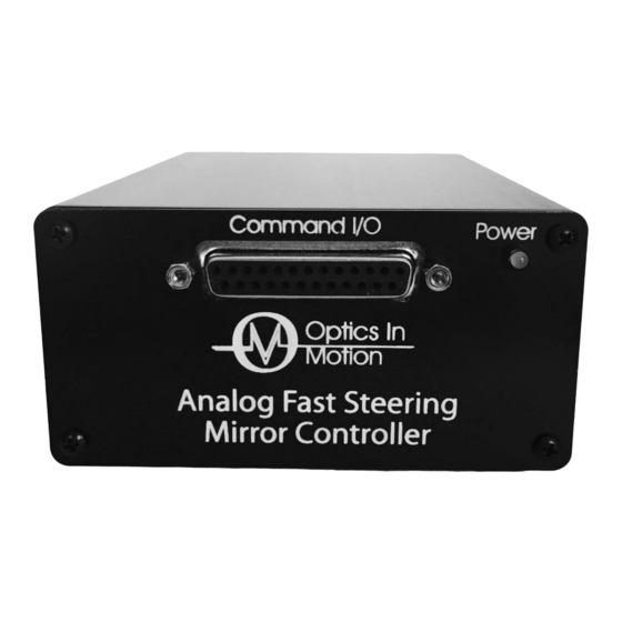
Summary of Contents for Optics-In-Motion OIMC100
- Page 1 Analog Controller User’s Manual Analog Fast Steering Mirror Controller Model OIMC100 May 29, 2015 Revision A...
- Page 2 Product Warranty Optics-In-Motion LLC warrants this product to be free from defects in material and workmanship for a period of 1 year from the date of shipment. If the product is found to be defective during the warranty period, the product will either be repaired or replaced at Optics-In-Motion’s option.
- Page 3 Table of Contents Page Product Warranty ................2 Table of Contents ................3 Mirror Controller: ................4 Figure 1: Adjustable PID ............. 4 Mirror Power Supply: ..............5 Figure 2: Controller Rear View ............. 5 Figure 3: Block diagram for X-axis control ........7 Figure 4: BNC to 25 PIN D Adapter PINOUT ........
- Page 4 Mirror Controller: The mirror controller electronics are housed in a remote enclosure connected to the FSM via a 6 foot cable. Mirror commands are input to the controller through a 25 socket D sub-miniature connector. The commands are differential signals representing the x and y mirror positions, scaled to the +/- 10 volt range.
- Page 5 and derivative (D) gain potentiometers (CCW to increase gain on these pots). The controller card is attached to another card via a ribbon cable which is hidden inside the controller box. The mirror can be driven while this card is pulled forward, allowing the user to optimize the PID values for a given step requirement while monitoring the position and error signals on a scope.
- Page 6 Command Connector Wiring Table 25-Socket Sub-miniature D Connector Number Signal Name Type Description X ERROR Output X summing junction error voltage output, difference between commanded and actual position. (referenced to ground) INT/EXT SWITCH Input Normally low TTL input. High level switches the position feedback input from local to external.
- Page 7 Mirror SERVO Head CONTROLLER X COMMAND COIL DRIVE INT/EXT SWITCH X POSITION (LOCAL) X POSITION (EXT) X POSITION OUTPUT Figure 3: Block diagram for X-axis control Figure 4: BNC to 25 PIN D Adapter PINOUT Page 7 of 7...

Need help?
Do you have a question about the OIMC100 and is the answer not in the manual?
Questions and answers