
Summary of Contents for JEON DG Series
- Page 1 Instruction Manual D103761X012 March 2021 DG Series Direct-Operated Regulators Manual...
-
Page 2: Table Of Contents
Call a qualified service person to service the unit. Installation, operation and maintenance procedures performed by unqualified person may result in improper adjustment and unsafe operation. Either condition may result in equipment damage or personal injury. Only a qualified person must install or service the DG Series regulator. -
Page 3: Introduction
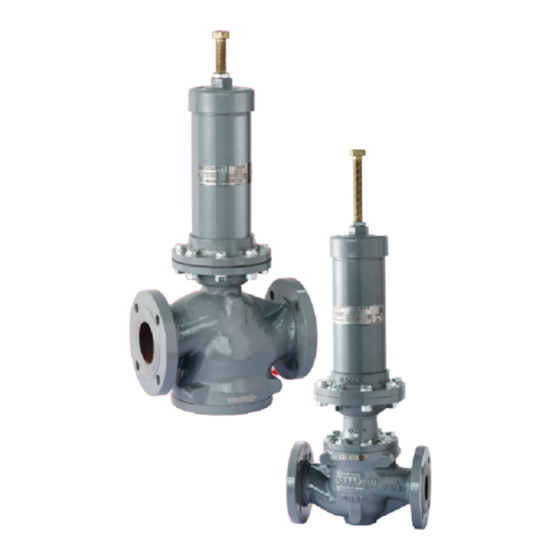
Pressure Reducing Series Regulators and Backpressure Series Regulators. Description DG Series are multipurpose direct-operated regulators that use fluid pressure to drive the actuator and automatically maintains the outlet pressure or inlet pressure constant. They are available in Pressure Reducing (PRV) and Backpressure (BPV) configurations to control outlet pressure or inlet pressure respectively. - Page 4 Inner Spring 316 SST 316 SST Seat 316 SST 316 SST Stem S31803 S31803 Table 3. Maximum Inlet/Outlet and Emergency Casing Pressure - DG Series PRV MAXIMUM INLET MAXIMUM OUTLET MAXIMUM EMERGENCY BODY ELASTOMER MEDIUM TEMPERATURE PRESSURE PRESSURE CASING PRESSURE...
- Page 5 DG Series Regulators Table 5. DG Series Pressure Reducing Control Ranges ELASTOMER/ SPRING CONTROL RANGE SPRING PART BODY ACTUATOR SPRING COLOR MEDIUM TYPE BODY SIZE TEMPERATURE NUMBER MATERIAL CONNECTION RANGE psig NBR (-29 to 80°C) PN 16/25/40 RF ERSA01273A0 White WCB or CF8M 0.15 to 0.3...
- Page 6 DG Series Regulators Table 6. DG Series Backpressure Control Ranges SPRING CONTROL RANGE SPRING PART SPRING BODY MEDIUM ELASTOMER/TEMPERATURE ACTUATOR BODY SIZE NUMBER COLOR MATERIAL CONNECTION TYPE RANGE psig NBR (-29 to 80°C) PN16/25/40 RF ERSA01273A0 White WCB or CF8M 0.15 to 0.32...
-
Page 7: Principle Of Operation
3. Principle of Operation DG Series PRV is a direct-operated pressure reducing regulator. When operating, fluid flows from the inlet chamber, up through the seat ring and cage and exits the outlet chamber. Downstream pressure is registered at the underside of the diaphragm through an external sensing line that is connected to the lower diaphragm casing. - Page 8 DG Series Regulators Figure 1. Operational Schematic of DG Series PRV ADJUSTING SCREW SPRING CASE CONTROL SPRING TRIM PARTS DIAPHRAGM BODY SENSING LINE INLET OUTLET INLET PRESSURE OUTLET PRESSURE ATMOSPHERIC PRESSURE INLET PRESSURE Figure 2. Operational Schematic of DG Series BPV...
-
Page 9: Installation
DG Series Regulators 4. Installation WARNING Personal injury or system damage may result if this regulator is installed, without appropriate overpressure protection, where service conditions could exceed the limits given in the Specifications section and/or regulator nameplate. Refer to Overpressure Protection section for recommendations on how to prevent service conditions from exceeding those limits. - Page 10 DG Series Regulators Figure 3. Installation Schematic for DG Series PRV PRESSURE DOWNSTREAM FILTER UPSTREAM GAUGE BLOCK VALVE BLOCK VALVE ≥ DN 10 ≥ DN 5 ≥ DN 5 INLET PRESSURE INLET PRESSURE OUTLET PRESSURE OUTLET PRESSURE ATMOSPHERIC PRESSURE ATMOSPHERIC PRESSURE Note: Optional Damper and Restrictor are available for various applications.
-
Page 11: Overpressure Protection
DG Series Pressure Reducing Regulator (PRV) DG Series pressure regulator have an outlet pressure rating lower than the inlet pressure rating. The recommended pressure limitations are stamped on the regulator nameplate. Some type of overpressure protection is needed if the actual inlet pressure can exceed the maximum operating outlet pressure rating. -
Page 12: Operating Of Pressure Reducing Regulator
Regulator operation below the limits specified in the Specifications section and regulator nameplate does not preclude the possibility of damage from external sources or from debris in the pipeline. DG Series Backpressure Regulator (BPV) Over-pressuring any portion of this equipment may result in equipment damage, leaks in the backpressure regulator or personal injury due to bursting of pressure-containing parts. -
Page 13: Maintenance
DG Series Regulators Figure 5. Diaphragm Case Figure 6. Spring Case ADJUSTING SCREW VENT HOLE PLUG LIQUID OPTION ONLY Pressure Adjustment To change the inlet pressure, unscrew the jam nut and slowly turn the adjusting screw (Figure 6) and set the inlet pressure to the desired setting, screw the jam nut. -
Page 14: Pressure Reducing Regulator Disassembly
2. Check DG Series BPV lock up pressure every 1 to 3 months: Slowly increase the inlet pressure until the relieving pressure starts to rise, then slowly decrease the inlet pressure until the valve closed, ensure the downstream pressure does not increase. - Page 15 DG Series Regulators Table 10. DG Series Pressure Reducing Regulator Assembly Torque TORQUE (N•m) PART NAME 1 In. 2 In. 3 In. 4 In. Bolts (key 16), M8×25 25 to 30 Bolts (key 42), M8×25 Nuts (key 40), M8 28 to 32...
- Page 16 DG Series Regulators Reassemble of the Pressure Reducing Regulator Make sure all the parts which needed to be maintenance are properly handled or replaced, then perform the following procedure: 24. Lubricate the O-ring (key 26), And assemble it onto the groove of the Plate/Gasket (key 27), add the Washer (key 28) and tighten the Nut (key 29) using torque values listed in Table 10.
- Page 17 DG Series Regulators 35. Lubricate the flange facing of Lower Casing (key 33) and the groove sealing face of Diaphragm Head (key 36), assemble the Diaphragm (key 39) onto the lower plate carefully. Make sure the pin holes on lower plate and diaphragm are aligned and make sure the bolts holes on diaphragm and bolts holes on flange faces are aligned.
-
Page 18: Backpressure Regulator Disassembly
Failure to properly follow maintenance installation procedures when replacing parts could result in regulator damage, personal injury and property damage from escaping process fluid or regulators separation during testing or after reinstallation in the pipe line. Table 11. DG Series Backpressure Regulator Assembly Torque TORQUE (N•m) PART NAME 1 In. - Page 19 DG Series Regulators Replacing Low-Pressure Actuator Diaphragm 5. Slowly screw out and remove Spring Case (key 49), loosen Nut (key 40), remove Washer (key 41) and bolt (key 42), carefully remove Upper Casing (key 43) and Base (key 47). 6. Loosen Nut (key 45) and disassembly the Base (key 47), remove and check the O-ring (key 46), replace it with new spare part if needed.
- Page 20 DG Series Regulators WARNING Personal injury, equipment damage or leakage due to escaping fluid may result if regulator bolts are not tightened to proper load. Always tighten bolts in an alternating pattern. 27. Lubricate the O-ring (key 10) and assemble it onto the outer groove of the Sleeve Guide (key 6); Lubricate O-ring (key 11) and assemble it onto the stage corner of the body (key 1).
-
Page 21: Parts Ordering
Emerson regulator, because they will void your warranty, might adversely affect the performance of the valve and could give rise to personal injury and property damage. Main Valve Parts of DG Series Pressure Reducing Regulator (Figure 7) Description... - Page 22 DG Series Regulators Description Part Number Description Part Number O-ring O-ring Nitrile (NBR) JI321265A38 Nitrile (NBR) Fluorocarbon (FKM) JI323265A38 DN 25 / NPS 1 JI321355040 Bolt DN 50 / NPS 2 JI321530060 Carbon steel DN 80 / NPS 3 JI321530A87 DN 25 / NPS 1 (8 pcs.
- Page 23 DG Series Regulators Description Part Number Description Part Number Seat Connector Pad (Low-Pressure Actuator Only) 316 Stainless steel / Nitrile (NBR) Steel 20# DN 25 / NPS 1 ERSA01781A0 DN 25/50/80 / NPS 1/2/3 ERSA03601A0 DN 50 / NPS 2...
- Page 24 DG Series Regulators Elastomer Spare Parts Kit for DG Series Pressure Reducing Regulator BODY SIZES SEALER MATERIAL ACTUATOR TYPE SPARE KIT CODE RDGP1X00NA0 RDGP2X00NA0 DOA330-1 (Low-Pressure) RDGP3X00NA0 RDGP4X00NA0 RDGP1X01NA0 RDGP2X01NA0 DOA330-2 Nitrile (NBR) (Low-Pressure) RDGP3X00NA0 RDGP4X00NA0 RDGP1X00NA1 RDGP2X00NA1 DOA180-1/DOA180-2 (High-Pressure)
- Page 25 DG Series Regulators Main Valve Parts of DG Series Backpressure Regulator (Figure 8) Description Part Number Description Part Number Elastomer Spare Parts Kit See following table Plane Washer Body See following table Carbon steel O-ring Low-Pressure Actuator Nitrile (NBR) DN 50 / NPS 2 (8 pcs. required)
- Page 26 DG Series Regulators Description Part Number Description Part Number Bolt O-ring Carbon steel Nitrile (NBR) JI321180A21 DN 25 / NPS 1 (4 pcs. required) JI1AD140035 Fluorocarbon (FKM) JI323180A21 DN 50 / NPS 2 (8 pcs. required) JI1AD120030 O-ring DN 80 / NPS 3 (8 pcs. required)
- Page 27 DG Series Regulators Elastomer Spare Parts Kit for DG Series Backpressure Regulator BODY SIZES SEALER MATERIAL ACTUATOR TYPE SPARE KIT CODE RDGB1X00NA0 RDGB2X00NA0 DOA330-1/DOA330-2 (Low-Pressure) RDGB3X00NA0 RDGB4X00NA0 Nitrile (NBR) RDGB1X00NA1 RDGB2X00NA1 DOA180-1/DOA180-2 (High-Pressure) RDGB3X00NA1 RDGB4X00NA1 RDGB1X00FA0 RDGB2X00FA0 DOA330-1/DOA330-2 (Low-Pressure) RDGB3X00FA0...
- Page 28 DG Series Regulators Actuator Parts (Low-Pressure Actuator – Figure 9, High-Pressure Actuator – Figure 10) Description Part Number Description Part Number Lower Casing Assemble Upper Spring Seat, Steel 45# ERSA01211A0 (Low-Pressure Actuator Only) Case Cover Q245R Carbon steel WCB Carbon steel...
- Page 29 DG Series Regulators Figure 7. Assemblies Schematic for DG Series PRV Pressure Reducing Regulator ASSEMBLIES OF CONNECTOR FOR PRV LOW-PRESSURE ACTUATOR (DN 25/50/80 / NPS 1/2/3)
- Page 30 DG Series Regulators Figure 8. Assemblies Schematic for DG BPV Backpressure Regulator Figure 9. Assemblies Schematic for Low-Pressure Actuator...
- Page 31 DG Series Regulators Figure 10. Assemblies Schematic for High-Pressure Actuator...
- Page 32 Jeon is a mark owned by one of the businesses of Emerson Automation Solutions. All other marks are the property of their respective owners. The contents of this publication are presented for informational purposes only, and while every effort has been made to ensure their accuracy, they are not to be construed as warranties or guarantees, express or implied, regarding the products or services described herein or their use or applicability.
Need help?
Do you have a question about the DG Series and is the answer not in the manual?
Questions and answers
Dear sir I interest for your product about regulator.
The JEON DG Series regulator is a multipurpose, direct-operated regulator that maintains constant outlet or inlet pressure. It is available in two configurations: Pressure Reducing (PRV) and Backpressure (BPV). Key specifications and features include:
- Body Sizes: DN 25, 50, 80, 100 / NPS 1, 2, 3, 4
- End Connection Styles: CL150 RF, CL300 RF, GB PN 16/25/40
- Materials:
- Body: WCB (Standard), CF8M (Optional)
- Diaphragm/Sealing Parts: NBR (Standard), FKM (Optional)
- Sleeve, Sleeve Guide, Cage, Inner Spring, Seat: 316 SST
- Stem: S31803
- Operating Features:
- High-capacity
- Fast response
- Tight shutoff
- Superior control and stability
- Applications: Industrial gas and liquid, including Nitrogen, Carbon Dioxide, Natural Gas, Oil, Water, Methanol, Alcohol, and Naphtha
- Temperature Limitations: Fluorocarbon (FKM) limited to 93°C (200°F) in hot water
- Safety Considerations: Only qualified personnel should install or service the unit to prevent hazardous conditions, equipment damage, or personal injury.
This answer is automatically generated