Table of Contents
Advertisement
Quick Links
Advertisement
Table of Contents

Summary of Contents for meteocontrol MX-Module RS485/422
- Page 1 MX-MODULE RS485/422 Quick Start Guide Version 20230210...
-
Page 2: Device Overview
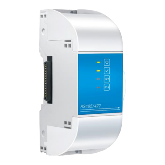
DEVICE OVERVIEW ñ LED: Power Status ò LED: Device Status ó LED: Bus-2 Connection ô LED: Bus-1 Connection Connector for blue’Log õ expansion ö Interface for RS485/422 – 1 ÷ Interface for RS485/422 - 2 ø Case lock... -
Page 3: Connection Order
CONNECTION ORDER When connecting MX-Modules to the blue’Log X basis device, the following order needs to be considered: The number of lines (incl. line with arrow) at the bottom of the front panel of the blue’Log and on the MX-Modules indicates the order of connection. -
Page 4: Installation
X basis device according to the manual. INSTALLATION The blue’Log X basis device ñ is expanded by the MX-Module RS485/422 ò with two additional interfaces ó and ô. blue’Log X basis device RS485/422 interface – 2 ñ ó RS485/422 interface – 1 ò ô MX-Module RS485/422... - Page 5 X basis Connect the MX-Module RS485/422 ò device ñ until no visible gap remains. Check for secure fit. and ò Interlock both modules (ñ ) by closing the previously opened case locks. Reattach the previously removed side cap to the right side of ...
-
Page 6: Pin Assignment
PIN ASSIGNMENT The following pin assignment can be applied to both (top and and ô bottom) RS485/422 interfaces (ó RS485 RS422 RS485 A (+) RS485 B (-) 6, 7, 8 *Refer to point 3... -
Page 7: Status Leds
STATUS-LEDS Symbol Explanation Green on: Module supplied with power Off: Error in power supply Green on: Standard mode: Module recognized Off: Error: Module not recognized Blinking orange Data transfer interface 2 active Steady orange Error on interface 2 light Blinking orange Data transfer interface 1 active Steady orange... - Page 8 Further information: www.meteocontrol.com Text and illustrations represent state-of-the-art technology at the time of printing Subject to technical modifications No liability for printing errors. Item number 832057 • Version 20230210...
Need help?
Do you have a question about the MX-Module RS485/422 and is the answer not in the manual?
Questions and answers