Table of Contents
Advertisement
Quick Links
Advertisement
Table of Contents

Summary of Contents for ECO Charge BMM
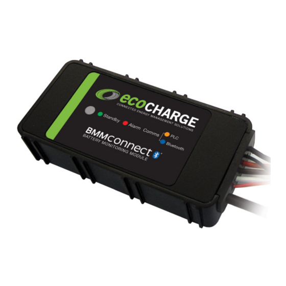
- Page 1 Battery Monitoring Module (BMM) Operator / Installer Manual...
-
Page 2: Warnings
WARNINGS Keep open fl ames Risk of battery away from batteries explosion. on charge. Be aware of Do not dispose battery fumes of batteries in and electrolyte. the garbage. Electrical hazard exists inside the Always recycle lead charger, do not acid batteries. -
Page 3: Table Of Contents
............................ LED Function Indicator ......................Voltage Imbalance Monitoring ..................Water Level Monitoring ......................Troubleshooting ........................Maintenance ..........................Service & Warranty ........................ Specifi cations ..........................BMM Serial Number BMM Part Number Date Supplied Battery Model Purchaser Purchase Invoice Number Fleet Number... -
Page 4: Overview
Overview This guide covers the installation of a BMM and confi guration of a BMM and associated XHF Series Charger. For instructions on the advanced functionality of the BMM data logging and analysis features available in the Charger Interface Software Manual, contact your EcoCharge dealer. -
Page 5: Installation
NOTE: Before attempting installation, please read through the complete installation instructions. The battery to be fi tted should be disconnected from any load prior to installation. Unit Location The BMM module is designed to sit directly on top of the battery surface. For optimum ®... - Page 6 It is recommended coat wire terminations with corrosion inhibitor before installation. Temperature Sensor The ideal location for the BMM temperature sensor is between the cells at the center of the battery. Depending battery type and construction, this may not be practical. The...
- Page 7 Installation of the electrolyte sensor requires care and consideration of the cell’s internal construction. If not required, the electrolyte sensor should be removed from the BMM by cutting the brown sensor wire at the entry point to the BMM module.
-
Page 8: Confi Guration
Confi guration BMM Confi guration Before use, both the BMM and the charger require confi guration to enable the Automatic Profi le Confi guration (APC) feature. The following instructions cover: 1. Connecting to the charger 2. Confi guring the BMM with the correct battery rating details. - Page 9 Click Use Values to populate the parameter fi elds with the template’s parameters. • To load the confi guration parameters into the BMM module, click Write Confi guration. • The BMM confi guration can be confi rmed by clicking Read Confi...
- Page 10 Confi guration - continued Charger Confi guration Confi guration of your XHF Series charger for Automatic Profi le Confi guration (APC) can be achieved by confi guration via the Charger Interface Software. • Connect your PC to the charger via USB and ensure the charger has AC supply.
-
Page 11: Operation
• Disconnect and reconnect the battery from the charger. - The charger will read the confi guration from the BMM module and the charge cycle will commence. Refer to your XHF Series charger documentation for information specifi c to your charger’s operation. -
Page 12: Voltage Imbalance Monitoring
Voltage Imbalance Monitoring Battery Equalization The BMM incorporates a Midpoint Voltage Sensor to allow monitoring of cell imbalance. • Voltage measured via the Midpoint Voltage Sensor on the battery is monitored to ensure it remains within 0.5V of half the battery voltage. -
Page 13: Water Level Monitoring
Water Level Monitoring If installed, the electrolyte sensor allows the BMM to monitor the battery electrolyte level. Should a low water level be detected, with Water Level Monitoring enabled the BMM can perform the following operations: • Display a Low Water alarm on the connected XHF series charger display (confi... -
Page 14: Troubleshooting
Always follow battery maintenance guidelines. ® No Bluetooth BMM is too far from Ensure the BMM is located near Connectivity device or enclosed a openings in the battery enclosure. conductive housing. Establish unobstructed line-of-sight path between BMM and reading device, and move as close as possible to the BMM. -
Page 15: Maintenance
Maintenance Once installed on the battery, the BMM module requires no maintenance other than to ensure the module and its various peripherals are secure and clear of excess battery acid. Routine checks on the condition of DC Supply and Midpoint Voltage terminals should be made and any accumulated corrosion removed according to the battery maintenance documentation. -
Page 16: Service & Warranty
Service & Warranty Service Contact your local EcoCharge Dealer for service or repair. Warranty Enatel Motive Power warrants the product is free from defects in material and workmanship and agrees to remedy any defect (or at its option replace the product) for a period of one year from the date of purchase. -
Page 17: Specifi Cations
Specifi cations Dimensions (in): 4.33L x 2.12W x 11.0H Toroid Internal Diameter (in): 0.74 Weight (oz): 11.6 Environmental Specifi cations Ambient Temp. Range: -5ºF to 122ºF (max. output power is derated above 122ºF) Storage Temp.: -68ºF to 158ºF Humidity: 5-95% RH (non-condensing) ®... - Page 18 Notes...
- Page 20 Contact Your Local Dealer: Manufactured by: Enatel Motive Power Ltd 66 Treffers Road, Christchurch 8042, New Zealand. Ph +64-3-366 4550 Fax +64-3-366 0884 info@enatel-mp.com www.enatel-mp.com Battery Monitoring Module (BMM) Operator/Installer Drawing: 150205A Copyright © 2015 Enatel Motive Power...
Need help?
Do you have a question about the BMM and is the answer not in the manual?
Questions and answers