Table of Contents
Advertisement
Quick Links
POWERCORE 30 OPERATOR MANUAL
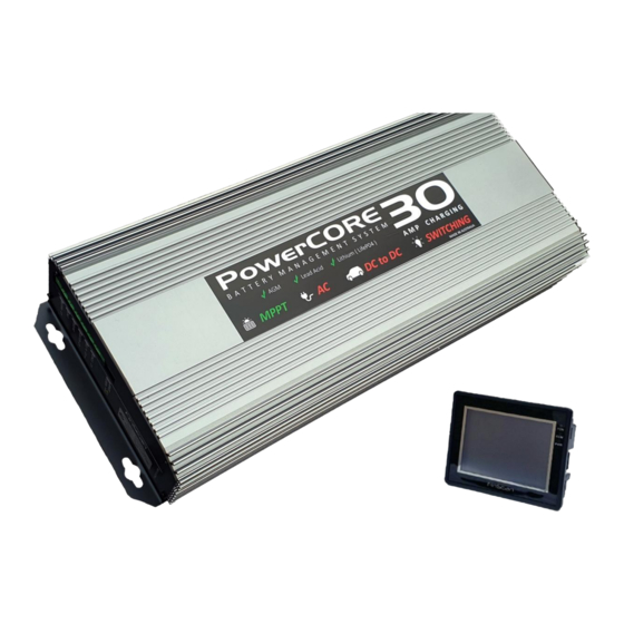
PowerCore 30
b a t t e r y m a n a g e m e n t s y s t e m
The PowerCore30 is a revolutionary total battery management and automation
system developed specifically for 4wd vehicles, RV's and campers. With powerful,
compact all in one features, the system will deliver a full continuous 30 Amps of
charging power from solar panels, vehicle DC to DC input and AC power. It will
manage dual battery systems, disconnect loads when batteries are low, and
maintain house and start batteries during storage. View and control the
PowerCore30 from it's remote touch screen control panel, or download the
PowerCore30 app and connect your smart phone.
1
Advertisement
Table of Contents

Summary of Contents for Australian Off Road PowerCore 30
- Page 1 POWERCORE 30 OPERATOR MANUAL PowerCore 30 b a t t e r y m a n a g e m e n t s y s t e m The PowerCore30 is a revolutionary total battery management and automation system developed specifically for 4wd vehicles, RV's and campers. With powerful, compact all in one features, the system will deliver a full continuous 30 Amps of charging power from solar panels, vehicle DC to DC input and AC power.
- Page 2 POWERCORE 30 OPERATOR MANUAL FEATURES ALL IN ONE compact 30 amp charger AC CHARGE - Charge from AC power source 30 amps DC_DC CHARGE - Charge from DC - DC vehicle power source 30 amps MPPT SOLAR CHARGE - Charge from Solar panel source via MPPT 30 amps ...
-
Page 3: Switching Operation
POWERCORE 30 OPERATOR MANUAL SWITCHING OPERATION All switching of lights and 12vDC power circuits ( with the exception of the dimming lights ) are operated and accessed via the switching icon from the home page Turning any light or power circuit on and off, is performed via the blue rectangle... -
Page 4: Dimming Operation
POWERCORE 30 OPERATOR MANUAL DIMMING OPERATION The PowerCORE has a dimming feature and is usually connected to an interior light to allow the operator to set the light level in the living space. Dimming can be accessed using the dimming icon from the home page. -
Page 5: Storage Mode
POWERCORE 30 OPERATOR MANUAL STORAGE MODE Storage mode is a feature that can be used when a camper or RV is put into storage. To turn storage mode on, press the Storage mode button on the home screen. To Turn storage mode off, press the button again so that it stops flashing. -
Page 6: Charging Operation
POWERCORE 30 OPERATOR MANUAL LITHIUM BATTERY JUMP START FEATURE A characteristic of some Lithium batteries, is that they will have their own internal battery management system. When a Lithium battery is excessively discharged, the internal battery management system will disconnect the battery terminals to preserve the battery and protect it from damage. - Page 7 POWERCORE 30 OPERATOR MANUAL moment in time , regardless of availability of multiple sources to the PowerCORE. All other source icons will be grayed out. SOLAR source - represents charging from solar panels VEHICLE source - represents charging from the vehicle alternator...
-
Page 8: Green Mode
POWERCORE 30 OPERATOR MANUAL GREEN MODE In addition to the default charge priority, a "Green Mode" feature is available on the battery page . Green mode will change the charging priority to select Solar as the first priority. This will change the behavior of PowerCORE to always attempt to provide charging from solar power first , if available. -
Page 9: Quiet Mode
POWERCORE 30 OPERATOR MANUAL QUIET MODE Quiet mode will reduce the speed of the PowerCORE cooling fan. This will reduce noise during operation for situations where PowerCORE is installed in an interior cavity. In extreme cases where ambient air temperature is high, and PowerCORE is operating at full capacity to charge a heavily discharged battery, PowerCORE may over ride Quiet mode temporarily. - Page 10 POWERCORE 30 OPERATOR MANUAL The BASIC screen will show information that is required to determine the battery state, at a glance. Information presented : 1. Charge source 2. State of Charge 3. Voltage 4. Hours of use remaining The ADVANCED screen will show more detailed battery data of a more technical nature.
-
Page 11: Error Messages
POWERCORE 30 OPERATOR MANUAL ERROR MESSAGES Error warnings displayed on the battery page will relate to the charging ability of PowerCORE. LOW VOLTAGE WARNING LOW VOLTAGE WARNING - The low voltage warning icon will appear when the battery voltage drops below a set threshold. -
Page 12: Over Temperature
POWERCORE 30 OPERATOR MANUAL NOTE : it is strongly recommended that your batteries be tested if you regularly have the battery temperature icon appear. OVER TEMPERATURE - The over temperature icon will appear if PowerCORE has reached a temperature that is too high to continue operating. -
Page 13: Tank Empty
POWERCORE 30 OPERATOR MANUAL OVER VOLTAGE - The over voltage error message will appear when PowerCORE detects that the battery voltage has exceeded 17.8 volts. PowerCORE cannot supply a voltage greater than 14.4 volts. TANK MONITORING The PowerCORE screen also monitors up to 5 x tanks, Depending on configuration, 2 to 5 tanks may appear. - Page 14 POWERCORE 30 OPERATOR MANUAL SYSTEM OVERIDE In the event of a system failure, there are mechanisms on the PowerCORE system to allow you to bypass the controls and apply emergency power to allow you to continue operating connected DC loads.
- Page 15 POWERCORE 30 OPERATOR MANUAL EXPANSION MODULE OVERIDE Located inside the expansion module, unscrew the plastic lid to reveal the fuses located inside. By moving the fuses for each circuit, the expansion module acts as a simple fuse box and applies fuse protected power to the connected DC load for emergency power.
- Page 16 POWERCORE 30 OPERATOR MANUAL SPECIFICATIONS AC Input voltage range 220 - 240vAC - 50-60Hz Output Current 30 amp continuous Charge voltage 14.4v Float voltage 13.7v DC - DC Input voltage 9 - 28v DC Solar Input 9 - 32v DC...
Need help?
Do you have a question about the PowerCore 30 and is the answer not in the manual?
Questions and answers