Table of Contents
Advertisement
Quick Links
Advertisement
Table of Contents

Summary of Contents for ELTEC miniHiPerCam
- Page 1 Hardware Manual Revision 2B elektronik mainz...
- Page 2 ELTEC products are not authorized for use as components in life support devices or systems intended for surgical implant into the body or intended to support or sustain life. Buyer agrees to notify ELTEC of any such intended end use whereupon ELTEC shall determine availability and suitability of its product or products for the use intended.
-
Page 3: Table Of Contents
1.4.8.2 Live: ................1—9 1.4.9 Lens Adjustment............1—9 1.4.10 Address Map ............1—10 1.4.11 COM1 Serial Port ............ 1—10 1.5 Connectors ..............1—11 1.6 System Parameters ............1—13 1.6.1 Environmental Conditions ......... 1—13 1.6.2 Power Requirements ..........1—13 1.6.3 Dimensions ..............1—13 miniHiPerCam... - Page 4 2.3 Updates ................2—1 2.4 Registry ................2—2 3 Installation................ 3—3 3.1 First Steps ..............3—3 3.2 Connect the miniHiPerCam to the Host ......3—3 3.3 Bootloader Configuration..........3—9 3.4 Cmd Shell ..............3—12 3.5 Connect to the miniHiPerCam Webserver ....3—14 3.6 Software Development ..........
- Page 5 Table 1—8: VGA Connector (DB15 female) ...... 1—11 Table 1—9: Serial Connector (DB15 female)..... 1—11 Table 1—10: COM1 Connector (DB9 male)....... 1—12 Table 1—11: Debug Connector (DB9 male) ...... 1—12 Table 1—12: Ethernet Connector (RJ45 Jack) ....1—12 Table 1—13: OV7610 Sensor Characteristics ....1—16 miniHiPerCam...
- Page 6 Table of Contents User's Manual List of Figures Figure 1—1: Block Diagram ..........1—4 Figure 1—2: miniHiPerCam Digital I/O......... 1—7 Figure 1—3: Dimensions ............ 1—14 Figure 1—4:Tripod Attachment ......... 1—14 Figure 3—1: Location of Connectors on the Back Panel ..3—4 Figure 3—2: Connecting miniHiPerCam to Host...
-
Page 7: Specification
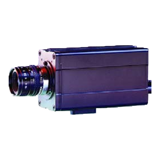
· Standard camera size. · GoAhead WebServer 1.2 General Description The miniHiPerCam is one of a growing number of intelligent cameras from ELTEC. It is a complete CMOS-based color matrix camera with an intelligent frame grabber together in a small housing. -
Page 8: Mechanical Specification
- lines are tightly packed. 1.3 Mechanical Specification The miniHiPerCam case has a small cross-section of 43,5 mm x 60 mm and a length of 96,5 mm, making it possible to stack several HiPerCams in space-constrained applications. The camera has a C- mount thread for lenses;... -
Page 9: I/O Mechanical
Signals serial I/O 15-pin 3-row D 2x RS232 serial Power Power +12V in Video out, digital I/O 15-pin 3-row D (VGA) Video out, Hsync out, Vsync out, 2 in , 2 out Ethernet RJ45 10BaseT Table 1—2: Connectors miniHiPerCam 1—3... -
Page 10: Technical Details
Figure 1—1: Block Diagram 1.4.1 CPU 1.4.1 CPU The miniHiPerCam CPU chip is a member of the PowerPC family of The miniHiPerCam CPU chip is a member of the PowerPC family of RISC processors. It is a full PowerPC with on-chip peripherals RISC processors. -
Page 11: Power Supply
1.4.2 Power Supply The power supply for the miniHiPerCam must deliver 8V to 24V with a minimum output power of 5W. The plug must have a diameter of 5.0mm to 5.5mm and a hole for a 2.1mm pin . -
Page 12: Table 1-4: Video Lut
100% green 100% blue (white) Table 1—5: Default LUT Setup Colors 241 to 255 are similar to the VGA colors. To save power and bus bandwidth it is recommended to disable the video output when it is not used. 1—6 miniHiPerCam... -
Page 13: Digital I/O
User's Manual Specification 1.4.4 Digital I/O The miniHiPerCam features two optoisolated inputs and two optoisolated outputs. The outputs are open collector type and can sink up to 120mA current. IN0 X401 Pin4 IN1 X401 Pin9 +3V3 PB25/IRQ1 PB24/IRQ5 +3V3 OUT0 X401 Pin11... -
Page 14: Memory / File System
Table 1—7: Main Memory 1.4.6 DRAM The main memory of the miniHiPerCam has a size of 16 Mbytes consisting of two 64 Mbit SDRAM chips. The memory timing is 5,1,1,1+1 for read and 3,1,1,1 for write bursts. This results in a bandwidth of 88 Mbytes/s for read and 133 Mbytes/s for write. -
Page 15: Flash Eprom
User's Manual Specification 1.4.7 Flash EPROM There are 8 Mbytes Flash EPROM installed on the miniHiPerCam. It holds the basic firmware for system initialization, booting, and configuration. After reset the Flash EPROM is mapped to $0000.0000. Since the Flash EPROM is only 16 bit wide, one burst read of the CPU lasts about 1.6 us. -
Page 16: Address Map
1.4.11 COM1 Serial Port The SCC3 of the MPC823 is used as universal serial port (COM1) that can be programed via standard Windows CE functions. Standard DB9 serial cables can be attached to the miniHiPerCam via V- CABL-196 or V-ADAP-300. 1—10... -
Page 17: Connectors
3 TXD 4 RXD SMC 5 TXD SMC 6 DSR 7 RTS Front View 8 CTS 9 CTS SMC 10 RI 11 RI 12 RTS SMC 13 DTR 14 GND 15 GND SMC Table 1—9: Serial Connector (DB15 female) miniHiPerCam 1—11... -
Page 18: Table 1-10: Com1 Connector (Db9 Male)
The two parts of V-CABL-196 have different lengths. The longer is the COM1 port while the shorter is the Debug port. Ethernet connector RJ45 1 +Tx 2 -Tx 3 +Rx Front View 6 -Rx Table 1—12: Ethernet Connector (RJ45 Jack) 1—12 miniHiPerCam... -
Page 19: System Parameters
· Typ. 300 mA at 12 V, max. 450 mA · Typ. 3,5 W, max. 5 W 1.6.3 Dimensions · 43,5 mm x 60 mm x 96,5 mm (without lens, tripod attachment, protrusion of connectors at back panel) · Weight: approx. 350 g miniHiPerCam 1—13... -
Page 20: Figure 1-3: Dimensions
Specification User's Manual Video Serial 60 mm Power Network 96,5 mm 43,5 mm Figure 1—3: Dimensions Figure 1—3: Dimensions 2,7 mm Thread 1/4" 30 mm 30 mm Figure 1—4:Tripod Attachment Figure 1—4:Tripod Attachment 1—14 miniHiPerC... -
Page 21: Regulations/Compliance
User's Manual Specification 1.6.4 Regulations/Compliance EN 50082-2 EN 55022 (unless otherwise noted) miniHiPerCam 1—15... -
Page 22: Image Sensor
User's Manual 1.7 Image Sensor 1.7 Image Sensor Currently one image sensor is supported by the miniHiPerCam: The Currently one image sensor is supported by the miniHiPerCam: The OmniVision OV7610 color sensor. The device is a complete camera OmniVision OV7610 color sensor. The device is a complete camera with digital interface supporting various data formats. -
Page 23: Operating System
Starting a kernel from the flash file system by the bootloader makes updating the kernel simple. When WinCE is running a new version can be copied to the flash file system from a host computer overriding the old one. After reboot the new kernel is started. miniHiPerCam 2—1... -
Page 24: Registry
The registry can be stored to the flash file system with a single routine provided in the SDK. The bootloader copies it to RAM where it is loaded by the WinCE kernel. For details concerning the bootloader and the SDK see the documentation provided on the SDK CD. 2—2 miniHiPerCam... -
Page 25: Installation
Host To setup the boot parameter or work with the serial shell the debug port of the miniHiPerCam must be connected to a terminal via the shorter part of V-CABL-196 and a serial null modem cable. To access the miniHiPerCam over a network, a network cable must be connected. -
Page 26: Figure 3-1: Location Of Connectors On The Back Panel
Installation User's Manual Video Serial Power Network Figure 3—1: Location of Connectors on the Back Panel 3—4 miniHiPerCam... -
Page 27: Figure 3-2: Connecting Minihipercam To Host (Without Hub)
Monitor VGA Monitor Mouse Video Cable Video Serial COM1 (SCC) COM2 COM1 Power Network Debug (SMC) 9-Pin D-Sub V-CABL-196 Network Interface 10Base2 10BaseT Power Supply 230V/50Hz 10BaseT crossed Cable 110V/60Hz Figure 3—2: Connecting miniHiPerCam to Host (without Hub) miniHiPerCam 3—5... -
Page 28: Figure 3-3: 10Baset Hub Network Connection
Installation User's Manual 10Base2 10BaseT Network 10BaseT Standard Cable 10BaseT Standard Cable 10BaseT 10Base2 Figure 3—3: 10BaseT Hub Network Connection 3—6 miniHiPerCam... -
Page 29: Figure 3-4: 10Baset/10Base2 Hub Network Connection
User's Manual Installation 10BaseT 10Base2 Network 10BaseT Standard Cable 10BaseT 10Base2 Figure 3—4: 10BaseT/10Base2 Hub Network Connection Take care that the 10Base2 network connection is correctly terminated at both ends. miniHiPerCam 3—7... -
Page 30: Figure 3-5: 10Baset/Aui Hub Network Connection
Installation User's Manual 10Base2 10BaseT Network 10BaseT Standard Cable 10BaseT 10Base2 Figure 3—5: 10BaseT/AUI Hub Network Connection 3—8 miniHiPerCam... -
Page 31: Bootloader Configuration
Installation 3.3 Bootloader Configuration It is important to set up the miniHiPerCam properly before using it the first time. Setup your terminal to use a 38400 baud connection with 8 data bits, 1 stop bit, no parity and no flow control. Starting the miniHiPerCam your terminal output should look like this. - Page 32 Entering no value and hitting "enter" will leave the values unchanged. "(Y/n)" means that current setting is "yes". By default the miniHiPerCam uses a DHCP server to get an IP address. If you have no DHCP server, you can enter a ethernet address and a corresponding subnet mask.
- Page 33 This is the very last help, if the emergency image can not be started. As you need additional tools which are not provided on the SDK CD to do this download ask the ELTEC support for help. eeDump This command shows the contents of the eeprom. This is needed for support purposes only.
-
Page 34: Cmd Shell
ELTEC V1.4 ( Fri May 18 09:06:46 2001 ) EL-Shell > The serial shell is written by ELTEC. See the online help shipped on the SDK CD for details. Here we will only show some commands needed to verify proper network connection. - Page 35 Reply from 194.0.0.150:Echo size=32 time=2ms TTL=128 Reply from 194.0.0.150:Echo size=32 time=2ms TTL=128 Reply from 194.0.0.150:Echo size=32 time=2ms TTL=128 Of course the miniHiPerCam can be "pinged" from the outside. The shell command "nc" can be used to connect a network drive on a remote computer.
-
Page 36: Connect To The Minihipercam Webserver
User's Manual 3.5 Connect to the miniHiPerCam Webserver By default a webserver is started on the miniHiPerCam. This server is described in detail in the online help. With help of this webserver the miniHiPerCam sensor can be configured and images can be transfered over the network with a browser. -
Page 37: Software Development
User's Manual Installation 3.6 Software Development To develop applications for the miniHiPerCam you need the Microsoft eMbedded Visual Tools 3.0. A detailed description and sample programs come with the SDK CD. miniHiPerCam 3—15... -
Page 38: Troubleshooting
You can gather the following information in your terminal program, copy the output and send it as email or fax to the ELTEC support. 3.7.1 Bootloader Version First boot the camera and enter the bootloader by hitting any key. If you do not see any output, you may not have connected the serial output properly to your modem. -
Page 39: Boot Parameters
Start serial shell (Y/n) ? Baudrate 115200 instead of 38400 (Y/n) ? 3.7.4 Kernel Version Just enter "quit" to leave the bootloader and start WinCE. A sample output is shown below. mHPC_Boot > q Really quit (Y/n) ? Bye ! miniHiPerCam 3—17... -
Page 40: Registry Contents
Going to launch WinCE image at 0x13868! Windows CE Kernel for PowerPC Built on May 5 2000 at 17:01:04 ELTEC V1.4 ( Fri May 18 09:06:46 2001 ) 3.7.5 Registry Contents You can use the program "regdump" to dump the contents of the registry. - Page 41 User's Manual Installation Notes: miniHiPerCam 3—19...
- Page 42 Installation User's Manual Notes: 3—20 miniHiPerCam...
Need help?
Do you have a question about the miniHiPerCam and is the answer not in the manual?
Questions and answers