Table of Contents
Advertisement
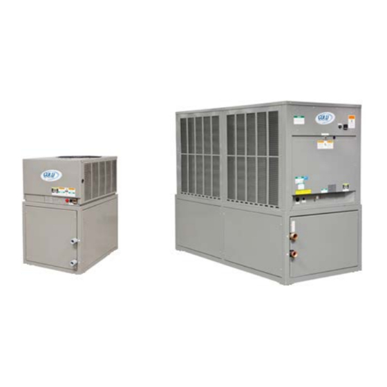
INSTALLATION, OPERATION, AND
MAINTENANCE INSTRUCTIONS
(ACWC-024-E-RF and ACWC-240-E indoor models shown)
AIR-COOLED, WATER CHILLERS
UP TO 240 kBTU/HR CAPACITY
Model#: ACWC-060-EM-DR-LT-M20-5
Serial#: XXXXXX-X
Marrone & Co., Inc.
14020 Interdrive West, Houston, Texas 77032 • Phone (800) 473-9178, (281) 227-8400
Fax (800) 473-9175, (281) 227-8404 • www.waterchillers.com
Advertisement
Table of Contents

Summary of Contents for Marrone & Co Cold Shot Chillers ACWC-060-EM-DR-LT-M20-5
- Page 1 INSTALLATION, OPERATION, AND MAINTENANCE INSTRUCTIONS (ACWC-024-E-RF and ACWC-240-E indoor models shown) AIR-COOLED, WATER CHILLERS UP TO 240 kBTU/HR CAPACITY Model#: ACWC-060-EM-DR-LT-M20-5 Serial#: XXXXXX-X Marrone & Co., Inc. 14020 Interdrive West, Houston, Texas 77032 • Phone (800) 473-9178, (281) 227-8400 Fax (800) 473-9175, (281) 227-8404 • www.waterchillers.com...
-
Page 2: Table Of Contents
MODEL NUMBER NOMENCLATURE ACWC Example Model#: Position: Position-Description 1. Model Type: ACWC: Air Cooled Water Chiller 2. Nominal Capacity in kBtu/hr 3. Series System 4. Flow Design: (_=Portable, ST=Stationary, RF=ReverseFlow, EXCH=HeatExchanger, DP=DualPump, DR=DualReturn) 5. Leaving Fluid Temperature (_=Standard, LT=LowTemperature-specify lowest temperature in °F) 6. -
Page 3: Important
I. IMPORTANT A. CODES AND REGULATIONS The United States Environmental Protection Agency (EPA) has issued various regulations regarding the introduction and disposal of refrigerants in this unit. Failure to follow these regulations may harm the environment and can lead to the imposition of substantial fines. Because these regulations may vary due to the passage of new laws we suggest that, any work on this unit be done by a certified technician. -
Page 4: Installation
II. INSTALLATION A. MOVEMENT/RIGGING 1. The preferred method for movement of the chiller while on the pallet is with forklift or pallet jack. 2. For rigging, overhead rigging with spreader bars above the unit is preferred. Protect unit from being crushed. CAUTION! All panels must be in place when rigging. -
Page 5: Split Systems (Remote Condenser Or Condensing Unit)
(6) Heat-trace cable. Protect any fluid system exposed to freezing ambient conditions. e) Systems with the process piping located above the chiller, should be aware of possible fluid returning to the chiller when the system is turned off. Typically, the chiller inlet/outlet piping is below the tank water level which will limit draining fluid to tank, however if the process piping is opened, the fluid may return to the tank and overflow. -
Page 6: Freeze Protection
5. IMPORTANT: Allowing the unit to operate with a voltage imbalance in excess of 2% may void the warranty. % Voltage Imbalance = 100 x (max voltage deviation from avg voltage) / (average voltage) Example: Expected supply voltage to unit is 240-3-60. Determine maximum deviation from average voltage: MAXIMUM DEVIATION: AVERAGE VOLTAGE:... -
Page 7: Performance
2. Automatic/Manual refill or change over systems should be cautious and attentive to the specific concentration of mixtures dilution over time. Measure the system’s concentration regularly. 3. Glycol concentrations affect cooling performance. As the temperature reduces, the fluid becomes thicker which may reduce heat transfer capabilities and reduces the circulating pump performance. -
Page 8: Pre-Startup
III. PRE-STARTUP 1. STARTUP CHECKLIST - Review and use. (Typically located at end of this manual.) 2. COMPRESSOR MOUNTS a) As shipped, the compressor(s) is held down by mounting bolts with vibration rubber grommets. b) Verify bolts are tight to base and that the compressor is able to move on the rubber grommets. (1) Single Compressor units: Verify that the shipping spacers (if installed) are removed from between the compressor bottom (or compressor plate) and the base of the unit. -
Page 9: Startup
IV. STARTUP 1. Verify installation is complete and all Pre-Startup steps are completed. 2. STARTUP CHECKLIST - Review and use. (Typically, located at end of this manual) 3. Attach refrigerant gauges to the appropriate service ports. 4. PUMP ONLY: Turn switch to Pump Only (or use local system pump) and operate for at least 15 minutes. -
Page 10: System Components: (See Your Chiller's Specification For Details.)
clear sight glass for optimum performance. Returning fluid temperature should not exceed 90°F on standard units or the chiller will cycle off on high head pressure and not run. Should this occur, allow water to cool down and restarting chiller once water is below 90°F. e) If sight glass is bubbly add to charge. - Page 11 8. FLOW SAFETY THERMOSTAT (FS): when the pressure drops below the set point and will automatically reset when pressure is above the non-adjustable reset setting. (See specifications for Figure 1 Low Flow details) / Freeze Safety 12. REFRIGERANT HIGH PRESSURE SAFETY (HPS) a) Monitors the pressure of the refrigerant and will automatically open when the pressure rises above the sensor fixed set...
- Page 12 Also, some temperature thermostats may supplied with a makeup water source of need to be adjusted. fluid for the tank. 17. PUMP (Depending on design) b) The makeup water (such as city water Systems with integral pump are typically supply) is connected the pipe setup to provide recirculating fluid for the...
-
Page 13: Maintenance (Basic Guide)
VI. MAINTENANCE (BASIC GUIDE) IMPORTANT • Always disconnect and lock out the electrical power source before attempting any connection, maintenance or repairs. Failure to do so can cause electrical shocks, burns and death. • All work must be performed by a qualified service person based on the local codes and regulations of the area. •... - Page 14 6. FLUID SYSTEM CONNECTIONS (INSPECT FOR b. Have a certified refrigeration technician check LEAKS OR LOOSE) the refrigeration system for proper operation. Visually check for fluid leaks throughout Leak check the unit, monitor operating system. Physically check for loose pipe pressures, and adjust as needed.
-
Page 15: Troubleshooting (Basic Guide)
VII. TROUBLESHOOTING (BASIC GUIDE) • The Troubleshooting Guide below is to be used as a guide only. All work should be performed by a trained technician and only with proper understanding of the system. Contact manufacturer for further assistance. • Prior to resetting any safety devices, ensure that the issue is resolved or use care in operating the system until the cause is determined. - Page 16 SYMPTOM AND PROBABLE CAUSE PROBABLE REMEDY UNIT OPERATES TOO LONG OR CONTINUOUSLY 9. Low refrigerant charge. 9. Add refrigerant. 10. Control contacts fused. 10. Replace control. 11. Air in system. 11. Purge and evacuate system. SYSTEM IS NOISY 1. Piping vibration. 1.
- Page 17 7. Motor defective. 7. Check motor winding for open or short. Replace motor/pump, if necessary. VOLTAGE IMBALANCE 1. Voltage Imbalance over 2% - Incoming Power 1. Main Incoming Voltage – - (Check Voltage at front and backside of each - A voltage imbalance may be an indication of loose contactor during operation.) wires/cable connections or faulty contactors.
- Page 18 TEMPERATURE CONTROLLER - CHROMALOX 6040 Reset or Auto/Manual Key Lower or Down Menu Key Raise or Up Menu Key Function Key 1/16 DI Figure 37 Typical front panel and keys Keypad Each instrument has either three or four switches, which are used to navigate through the user menus and make adjustment to the parameter values.
- Page 19 6 Messages and Error Indications The following displays are shown when an error occurs or a hardware change is detected. Table 4. Error/Faults conditions Lower Error/Faults Display Conditions Upper display (where fitted) Configuration & Setup is required. Seen at first turn on or if Goto Conf hardware configuration changed.
- Page 20 P266 Series Single-Phase Condenser Fan Speed Control Abbreviated Version Installation Instructions P266xxx-x Part No. 24-7664-2705, Rev. B Issued April 29, 2009 Supersedes January 21, 2009 Application IMPORTANT: Use this P266 Single-Phase Condenser Fan Speed Control only as an operating control. Where failure or malfunction of the P266 fan speed control could lead to personal injury or property damage to the controlled equipment or other property, additional precautions must be...
- Page 21 Refer to the P499 Series Electronic Pressure P266 Electronic Pressure Transducers P266 controls are designed to reference either one or Transducers Product/Technical Bulletin (LIT-12011190) for information on installing P266 transducers. two Johnson Controls P266 Electronic Pressure Transducers to monitor condenser pressure. Table 3: P266SNR Electronic Pressure Transducers P266 transducers are specialized versions of the...
- Page 22 McDonnell & Miller Flow Switches - Liquid Adjustment Adjustment is necessary only if required flow/no flow set- points are above factory set minimum. a. Turn off power. Remove electric enclosure cover. COMMON b. Turn the adjusting screw clockwise to increase setpoint. NORMALLY IMPORTANT: Do not attempt to lower flow switch OPEN...
- Page 23 ICM45 50 Three Phas se Voltage M Monitors Programmab ble, 25‐Fault Me emory, Protects motors from pr remature failure e and burnouts MODE OF OPERATION At powe er up, the ICM 450 evaluates the incoming p power for prope er phase seque ence, amplitude e, and symmetr ry (voltage unbalance). I If the three pha se input at the ...
- Page 24 Fault Conditions Press and release fault button to scroll through all saved faults. Note: For initial setup, press and hold FAULT for 5 seconds to remove any previously stored faults. Fault Problem Corrective Action Back Phase Not all three of the phases 1. Re‐energize the contactor. Loss on the load side are 2. If the fault reappears after the load energizes: present a. Turn all power OFF b. Check all load side connections c. Check the contacts of the contactor for debris or excess carbon. Back Phase Loads 1, 2, or 3 are not in 1. Turn OFF all power. Rev sequence 2. Swap any 2 phases on the load side of the unit only (example: swap load 1 and load 2) * (not 120º phase shifted) 3. Re‐apply power. Back Phase A voltage unbalance 1. Press the READ button to observe the present load voltages. Check system for Unbal between the three load unbalance cause. phases exceeds the 2. Increase the fault interrogation time if necessary. unbalance setpoint 3. Increase the percent unbalance setting if necessary. Front Over Average phase‐phase 1. Check system for over‐voltage cause. ...
- Page 25 ICM 450C; Parameter Settings and Wiring Diagram For 230-460 Volt Units, 24 Volt Control Parameters Parameter Description Range Factory Setting Line Voltage Average phase to phase line voltage 190-630 220V 460V Delay On Break Amount of time between the load de-energizing and re- energizing 0-10 minutes 3 minutes** 3 minutes**...
- Page 26 TECHNICAL SPECIFICATION Model: ACWC-060-E-__ Description: Single stage air-cooled portable water chiller system. System will provide approximately 60,000 Btu/hr of cooling capacity with a leaving fluid temperature of 50°F and an ambient air temperature of 95°F. CAPACITY 60,000 BTU /HR ±5% AT 50° LCWT / 95°F AMBIENT COMPRESSOR / REFRIGERANT HERMETIC SCROLL / R410A 1 / 3500 CFM...
- Page 27 PUOD-000-001-2-0 Performance Curve and Data Sheet 1-Hp (single phase-115-230V) ODP Motor / Pump with 4.75”Impeller/0.160 Vane ASP-SSPC Pump/Motor Assembly If needed, the pump label is located on the pump casing near outlet port under the insulation. Carefully pull insulation up near the unglued section.
- Page 28 FRONT RIGHT SIDE VIEW VIEW Access Panel Temperature Controller Control Switch (PumpOnly/Off/Cooling) 60.2in. 66.7in. Insulated Tank with Lid "Y" Strainer (inside) "Y" Strainer (inside) (inside) Tank Fill Port Secondary Inlet Primary Inlet (MNPT) Capped (MNPT) to tank Outlet (MNPT) Tank Level Sight glass Chiller Pump (inside)
- Page 29 BACK LEFT SIDE VIEW VIEW Temperature Controller Control Switches 60.0in. Insulated Tank with Lid (inside) Tank Fill Port Tank Level Sight glass Tank Drain 6.5in. Casters Casters (Fixed) 32.0in. 44.0in. (Swivel) GENERAL NOTES Specifications subject to change without notice. Shown with Full Metal Cabinet included. Casters are standard on indoor units optional for outdoors, SHOP DRAWING check work order for application.
- Page 30 TOP VIEW BOTTOM VIEW Anchor Plates (Standard) – Holes drilled , Optional 44.0in. Control Switch & Temperature Controller 2.8in. 2.8in. Electrical Panel Front GENERAL NOTES Specifications subject to change without notice. Shown with Full Metal Cabinet included. With Secondondary no pressure return Casters are standard on indoor units optional for outdoors, SIZE DIMENSION NOTES...
- Page 31 Tandem Compressor Models only Compressor Low Pressure Switch Suction Line Flow Safety Thermostat Service Valve/Port Air Cooled Condenser Compressor Sensing Bulb Tube Suction Condenser Coils Accumulator* Evaporator CHILLER (Fluid System) Hot Gas Bypass Additional Valve Fans* (Optional) Head Pressure High Pressure Sensing Bulb Tube Liquid Line Switch...
- Page 32 STAINLESS STEEL Customer TANK WITH SHOE BOX Process STAINLESS STEEL/ SECONDARY COPPER BRAZED TANK PLATE EVAPORATOR RETURN FLOW SWITCH STRAINER WATER RETURN (IN) Heat PIPE Exchanger STRAINER Note: MANUAL *Flow Switch typical on BYPASS Low Temp. Low Ambient units. WATER SUPPLY (OUT) GLOBE VALVE...
- Page 33 GROUNDING LUG GRN/YEL COMPRESSOR POWER SUPPLY FIELD L2/N SUPPLIED DISCONNECT MOTOR P266 Used with low ambient kit only Used with low ambient kit only BLK/WHT CHILLER PUMP FB-1 WITH REMOTE Remove jumper for remote on/off ON/OFF ONLY “NOTE” connect TB1 #1 and TB1 #2 to a 208/230V CONNECT FOR “DRY”...
- Page 34 TYPICAL START-UP CHECK LIST EQUIPMENT MODEL# SERIAL# OWNER NAME PHONE# ADDRESS CITY STATE INSTALLING CONTRACTOR PHONE# ADDRESS CITY STATE START-UP PERFORMED BY PHONE# * Designates Pre-Startup items. To be performed before Startup of system. 1. *Manual referred to for details on installation and startup (IMPORTANT). 2.
Need help?
Do you have a question about the Cold Shot Chillers ACWC-060-EM-DR-LT-M20-5 and is the answer not in the manual?
Questions and answers