Advertisement
Quick Links
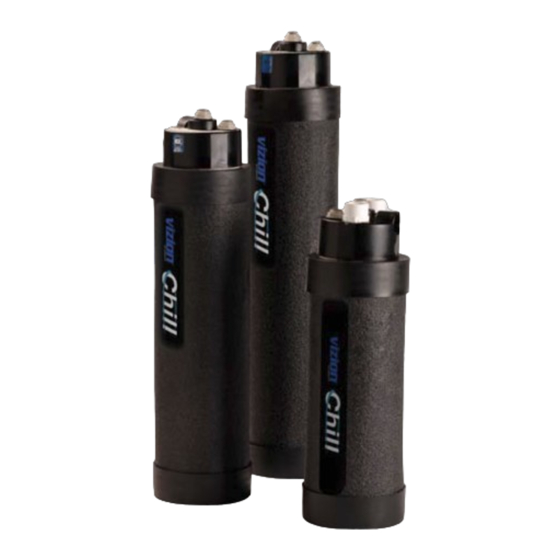
Maximicer
Water Chilling System
Installation Guide for Models
ICE-1000, ICE-1800, & ICE-H
Equipment Required:
Tools:
Materials:
Tubing Cutter
10 ft of 3/8" (0.95cm) Copper Tubing
PVC Cutter
10 ft of 3/4" (1.91cm) PVC Pipe
Power Screwdriver or Drill
(1) PVC 3/4" (1.91cm) ʻTʼConnection
Channel-lock Pliers
(5) PVC 3/4" (1.91cm) 90˚ Connections
Adjustable Wrench
(2) Brass 3/8" (0.95cm) Tubing Unions
Measuring Tape
PVC Cement
Note: ICE-H model requires the use of
1/2" (1.27cm) copper tubing and unions
Average Installation Time: 45 to 60 minutes
®
Installation Guide
This guide shows how to install the ICE-1000, ICE-1800, and ICE-H
models of the Maximicer Water Chilling System. If you encounter any
problems after installing Maximicer, refer to Troubleshooting on the last
page of this guide, or call for technical assistance at (800) 289-9098.
Maximicer Connections
#2
#1
Fresh Water Inlet
(From Wall or Filter)
Fresh Water Connections
Maximicer units use Super Speedfit® tubing fittings for the fresh water
line connections that require no tools. Tubing (copper or plastic) is simply
inserted into the fitting collet to effect a secure connection.
The tubing should be inserted
Secure connections are simple
aproximately 3/4" (1.91cm)
until it bottoms completely in
the fitting to insure that there
Cut the tube square and push past
will be no leaks.
Tube is secured in position
The tubing end to be inserted
should be straight and have a
Disconnection is just as easy
clean round cut. If the tubing
Push collet against body
is out-of-round, then carefully
make a new cut before insert-
ing into the fitting.
Slide tube out of fitting
Sump Water Connections
Maximicer units require the use of 3/4" (1.91cm) PVC pipe for the sump
water connections. It is important to glue all connections with PVC ce-
ment. Follow the specific installation procedures to make certain there will
not be a vacuum block or any reduction in water flow to the floor drain.
Fresh Water Outlet
(To Ice Machine)
#3
Sump Water Discharge Inlet
(From Ice Machine)
#4
Sump Water Outlet
(To Floor Drain)
the O-ring to the tube stop
Advertisement

Summary of Contents for Maximicer ICE-1000
- Page 1 1/2” (1.27cm) copper tubing and unions Sump Water Connections Maximicer units require the use of 3/4” (1.91cm) PVC pipe for the sump Average Installation Time: 45 to 60 minutes water connections. It is important to glue all connections with PVC ce- ment.
- Page 2 Attach a PVC line from the vent pipe at the ice machine drain outlet Maximicer should be installed behind or to the side of the ice machine bin to the upper PVC connection on the at least 6 inches (15cm) beneath the height of the ice machineʼs sump wa- Maximicer (connection #3).
- Page 3 Check the PVC drain lines for leaks by pouring water through the technical assistance. vent pipe until it is seen exiting the Maximicer into the floor drain, then turn the ice machine power ON. If you encounter any PVC drain water problems refer to the Troubleshooting section.
Need help?
Do you have a question about the ICE-1000 and is the answer not in the manual?
Questions and answers