Table of Contents
Advertisement
Quick Links
Advertisement
Table of Contents

Summary of Contents for Emtron CAN
- Page 1 Emtron CAN Gauge USER MANUAL Rev 1.0...
- Page 2 EMTRON ED5 USER MANUAL WWW.EMTRON.WORLD Kit Contents When purchasing the Emtron CAN Gauge the following items are included: • 1x Emtron CAN Gauge • 1 x Mounting Bracket • 2 x Mounting Bracket thumbscrews • 1 x Unterminated standard flying loom...
-
Page 3: Table Of Contents
3.3 ECU Terminals, Connector, & Installation tools: ............. 5 4.0 Wiring ........................... 6 4.1 CAN Guage Wiring......................6 4.2 CAN Bus Wiring ........................ 7 4.3 Illumination Signal Wiring ....................9 5.0 Gauge ART Application ...................... 10 5.1 Create Configuration ...................... 10 5.2 Save &... -
Page 4: Description
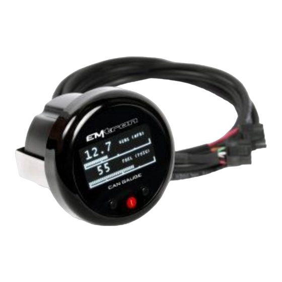
EMTRON ED5 USER MANUAL WWW.EMTRON.WORLD 1.0 Description The Emtron CAN Gauge by Gauge ART is a compact 52mm OLED gauge that connects to all Emtron ECU’s to display real-time data from CAN broadcasts. It is also compatible with aftermarket and factory ECU’s. -
Page 5: Specification
• Wireless wifi configuration • Connect more than one unit • Runtime channel names user definable • User defined channels can be displayed • OLED Display • 1,2 or 4 channel gauge layouts available • Up to 10 different pages available Inputs •... -
Page 6: Requirements
Smartphone or tablet with Apple iOS or Android v4.4 or later. 3.3 ECU Terminals, Connector, & Installation tools: The Emtron CAN Gauge includes an unterminated flying loom that will require connection to a power source and the ECU CAN bus. -
Page 7: Wiring
EMTRON ED5 USER MANUAL WWW.EMTRON.WORLD 4.0 Wiring 4.1 CAN Guage Wiring Wire Function 14 V Supply Black Ground 14 V Illumination Orange CAN Hi White Green CAN Lo Table 4.1. CAN Gauge Wiring © EMTRON AUSTRALIA PTY LTD MARCH 2018... -
Page 8: Can Bus Wiring
EMTRON ED5 USER MANUAL WWW.EMTRON.WORLD 4.2 CAN Bus Wiring The CAN Gauge includes a user-configurable 120 ohm terminating resistor jumper. The resistor is enabled when the jumper is in place. © EMTRON AUSTRALIA PTY LTD MARCH 2018... - Page 9 WWW.EMTRON.WORLD CAN bus wiring precautions ▪ CAN Bus High and Low are differential signals, so twisted pair MUST be used. Failing to do so will compromise the entire CAN Bus System. ▪ In some extreme environments, shielded twisted pair may be required to help with reliability and data integrity.
-
Page 10: Illumination Signal Wiring
Figure 4.3. CAN Bus Wiring Example. Stub Length less than 0.3m 4.3 Illumination Signal Wiring The CAN Gauge can dim illumination during night when the parking lights are on. Using the factory service manual, find a wire in the interior that switches to +12V power when the parking lights are on. -
Page 11: Gauge Art Application
Tap Create Configuration. Select ECU type and tap Next. The gaugeART CAN Gauge allows you to create up to 10 pages of gauge layouts in 1, 2, or 4 gauge layouts. Tap the centre of the screen for Gauge Screen Setup. On this screen, select a channel, configure graph range, update speed, warnings, and gauge labels (e.g. -
Page 12: Save & Send Configuration
Select “Emtron”. Previously saved files will be shown in the second drop down. Click load to open the file. To Edit your saved configuration, tap edit once loaded. To program, tap Send Configuration. © EMTRON AUSTRALIA PTY LTD MARCH 2018... -
Page 13: Emtune Settings
Open the first available Channel. If there is nothing else already configured on the CAN bus then CAN 1 Channel 1 would be the first available channel. If this channel is already used, then simply select a channel that is free. The CAN 1 channel number selection will have no effect on the operation Set CAN 1 –... -
Page 14: Ordering Information
WWW.EMTRON.WORLD Store setting changes permanently in the ECU by pressing F4. Switch power OFF and ON to the ECU to ensure the updated CAN bus settings have been initialised. The Can Gauge should now be receiving and displaying live runtimes. - Page 15 EMTRON ED5 USER MANUAL WWW.EMTRON.WORLD Emtron Australia Pty Ltd Unit 8, 36 Lidco Street Arndell Park NSW 2148 Australia (See the www for contact information) www.emtron.world www.emtronaustralia.com.au © EMTRON AUSTRALIA PTY LTD MARCH 2018...
Need help?
Do you have a question about the CAN and is the answer not in the manual?
Questions and answers