
Summary of Contents for Valdemar Energy V1 Series
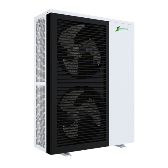
- Page 1 EVI DC Inverter Heat Pump (with WIFI APP) OPERATING INSTRUCTION MANUAL---Valdemar Energy Denmark ---www.valdemarenergy.com--- IMPORTANT SAFETY INSTRUCTIONS READ AND FOLLOW ALL INSTRUCTIONS SAVE THESE INSTRUCTIONS...
-
Page 2: Table Of Contents
Table of Contents IMPORTANT SAFETY PRECAUTIONS ................. . - 2 - Section 1 Introduction.............. - 3 - Product Overview ........................- 3 - General Features ........................- 3 - Section 2 Installation.............. - 4 - Materials Needed for Installation ....................- 4 - Installation Location ......................... -
Page 3: Important Safety Precautions
IMPORTANT SAFETY PRECAUTIONS Important Notice: This guide provides installation and operation instructions for the EVI DC Inverter Air Source Heat Pump. Consult the seller with any questions regarding this equipment. Attention Installer: This guide contains important information about the installation, operation and safe use of this product. -
Page 4: Introduction
Heat Pump Energy Saving Tips If you do not plan to use hot water for a prolonged period, then you might choose to turn the heat pump off or decrease the temp. setting of the control several degrees to minimize energy consumption. -
Page 5: Installation
4. No potential danger of any inflammable, gas poisoning, explosion, fire, electrical shock which are associated with other heating systems. 5. A digital controller is incorporated to maintain the desired water temp. 6. Long-life and corrosion resistant composite cabinet stands up to severe climates. 7. - Page 6 Product Model V1-08 V1-13 Heating Capacity Range 1.57~8.40 4.40~13.00 (kW) Heating Input Range (kW) 0.32~1.87 0.90~3.02 Heating Current Range (A) 1.42~8.30 1.39~4.68 COP Range 4.49~4.91 4.30~4.90 Cooling Capacity Range (kW) 0.99~6.22 2.80~8.20 Cooling Input Power (kW) 0.29~2.18 0.85~3.31 Cooling Current Range (A) 1.28~9.67 1.32~5.13 EER Range...
- Page 7 Product Model V1-18 V1-23 V1-28 V1-35 Heating Capacity Range 5.9~18.2 7.5~23.0 10.2~28.0 12.8~35.0 (kW) Heating Input Range (kW) 1.20~4.11 1.53~5.23 2.07~6.36 2.61~7.99 Heating Current Range (A) 1.86~6.37 2.37~8.11 3.70~11.4 4.67~14.3 COP Range 4.43~4.92 4.40~4.90 4.40~4.92 4.38~4.90 Cooling Capacity Range (kW) 3.81~11.53 4.73~14.6 6.54~19.8...
- Page 8 Correct installation is required to ensure safe operation. The requirements for heat pumps include the following: Dimensions for critical connections. Field assembly (if required). Appropriate site location and clearances. Proper electrical wiring. Adequate water flow. This manual provides the information needed to meet these requirements. Review all application and installation procedures completely before continuing the installation.
- Page 9 V1-18 V1-23 V1-28 V1-35 - 8 -...
- Page 10 Exploded view V1-08 - 9 -...
- Page 11 V1-13 - 10 -...
- Page 12 V1-18/23 - 11 -...
- Page 13 V1-28/35 - 12 -...
-
Page 14: Installation Location
Installation Location CAUTION! 1. DO NOT install the heat pump near to hazardous materials and places 2. DO NOT install the heat pump under deep sloping roofs without gutters which will allow rainwater, mixed with debris, to be forced through the unit. 3. -
Page 15: Drainage And Condensation
The plumbing pipes must be installed with proper support to prevent possible damage due to vibration. Running water pressure should be kept over 196kpa. Otherwise, booster pump should be installed. The acceptable operating voltage range should be within ±10% of the rated voltage. ⚫... - Page 16 Fig ure 2 Figure 3 - 15 -...
- Page 17 Figure 4 Figure 5 Figure 6 2. For only hot water installation 1) System installation diagram (see Figure 7). 2) Electrical wiring diagram (see Figure 8). (If you do not need to install auxiliary heating, DO not connect point 1,4 AC contactor) 3) Controller panel setting (see Figure 9).
- Page 18 Figure 7 Figure 8 - 17 -...
- Page 19 Figure 9 3. For heating and cooling installation 1) System installation diagram (see Figure 10). 2) Electrical wiring diagram (see Figure 11). (If you do not need to install auxiliary heating, DO not connect point 1,4 AC contactor) 3) Controller panel setting ( see Figure 12, and Figure 13). The inlet water setting temp. of the heating or cooling mode can be adjusted by Target temperature setting interface.
- Page 20 Figure 11 Figure 12 Figure 13 - 19 -...
-
Page 21: Water Connections
Water Connections Water Connections at the Heat Pump Quick Connect fittings are recommended to be installed on the water inlet and outlet connections. It is recommended to use stainless steel or PPR pipes for the heat pump plumbing. The water inlet and outlet connection to the heat pump accepts stainless steel or PPR pipe fittings. -
Page 22: Power Supply
Power Supply If the supply voltage is too low or too high, it can cause damage and/or result in unstable operation of the heat pump unit, due to high in rush currents on start up. The minimum starting voltage should be above 90% of rated voltage. The acceptable operating voltage range should be within ±10% of the rated voltage. -
Page 23: Electrical Wiring Diagram
Electrical Wiring Diagram 1. Single phase system (V1-08) - 22 -... - Page 24 2. Three phase system (V1-13/18/23) - 23 -...
- Page 25 3. Three phase system (V1-28/35) - 24 -...
-
Page 26: Operating Heat Pump
Section 3 Operating Heat Pump Controller Panel Turn off status (All buttons in gray) Turn on status (All buttons in orange) 1. Display Icon Mode Meaning Heating mode Hot water mode Cooling mode Heating and Hot water Mode (Hot water function as priority) Cooling and Hot water Mode (Hot water function as priority) Vacation mode... -
Page 27: Definition Of Buttons
2. Definition of Buttons Button Description Function On/off turn on or turn off the heat pump. Mode switch the operating mode of the heat pump. Timer set timer switch and working weekdays. query running parameters, check and set system parameters, Setting error code records, Wifi connection, etc. -
Page 28: Wire Controller Operation
3. Wire Controller Operation START / STOP THE HEAT PUMP ◎ In the main interface, press ON/OFF button for around 1 seconds to turn on or turn off the heat pump. Turn off status (All buttons in gray) Turn on status (All buttons in orange) RUNNING MODE SETTING: ◎When the heat pumps are ON and in the main interface, press MODE button for around 1 seconds to switch the running modes. - Page 29 OPERATING MODE SELECTION ◎Click“ OPERATING MODE” on the Setting interface to enter Operating mode selection interface; ◎Operating mode description:In the normal mode, Heat pump has Smart, Powerful, & Silent Operating states to choose. ◎Vacation mode description: When this mode is enabled, the heat pump runs in heating mode only, with a Target temperature of vacation Set;...
- Page 30 SET TARGET WATER TEMPERATURE ◎In the main interface, press SET button to enter Target temp. setting interface (as below). Typing the target temp. value, then press “Enter” to save and exit, or press “Esc” to exit without saving. CLOCK SETTING: ◎In the main interface, press to enter clock setting interface as below.
- Page 31 TIMER SETTING: ◎In the main interface, press TIMER button to enter timing setting interface. ◎In the WEEK column, users can select which weekdays to perform timer switch. When the weekday button (From MON. to SUN.) turns orange, the timer will perform on that day. When the weekday button turns gray, the timer will not perform on that day.
- Page 32 ◎List of operation parameters Code Description Remark Water inlet temp. -30~99℃ Water outlet temp. -30~99℃ Ambient temp. -30~99℃ Exhaust gas temp. 0~125℃ Return gas temp. -30~99℃ Evaporator coil temp. -30~99℃ Inlet temp. of economizer -30~99℃ Outlet temp. of economizer -30~99℃ Cooling coil temp.
- Page 33 definition, range and default value. ◎ List of system parameters Code Definition Settable Range Default Temp difference of return water and 2℃~18℃ 2℃ cooling target temp Temp difference of return water and hot 2℃~18℃ 5℃ water target temp Hot water setting temp. 28℃~60℃...
- Page 34 Ambient temp. for defrosting 0℃~20℃ 17℃ 0~30 days High temperature disinfection cycle Disinfection function is not days executed when set to 0 High temperature disinfection start time 0~23:00 High temperature disinfection sustaining 0~90min time High temperature disinfection setting 0~90℃ 70℃ temperature Heat pump’s setting temperature for 40~60℃...
- Page 35 forced to turn on. ◎ During the Antisepsis process, if the water tank temperature > 60℃ (the maximum settable temperature), then the compressor will not start, but only start electric heating; if the water tank temperature ≤55℃, both the compressor and electric heater will start. ◎...
-
Page 36: General Operating Guide
1) In hot water mode. 2) The compressor runs for P27(30)minutes. 3) There is a demand for hot water, and the temperature of the water tank is ≤55℃; 4) The pump is running ◎ Exit condition (only need to meet any one of the below conditions) 1) When the heat pump is performing cooling mode / hot water mode. -
Page 37: Users' Guide
6. Running checks (according to the following data to check if the unit running is normal) After unit normal running, check the following item: a. Input and output water temp. b. cycle water flow of the side c. running electric current of compressor and fan d. - Page 38 use. G. If the unit is soaking, please contact the supplier, factory or company of installment before use. - 37 -...
-
Page 39: General Maintenance
H. It’s forbidden to insert any tools through the fence of the unit. The fan can cause serious harm if handled incorrectly. Contact a specialist for further assistance. I. To avoid electric shock or cause fire, don’t store and use fixture, oil paint and petrol etc. combustible gas or liquid around the unit;... - Page 40 Er 34 The temp. of frequency conversion module is too high Er 42 Cooling coil temp. sensor failure Inlet temp. fault of economizer Er 62 Er 63 Outlet temp. failure of economizer Er 64 DC fan 1 fault Er 66 DC fan 2 fault Er 67 Low pressure switch failure...
-
Page 41: Owner Inspection
Error name description Solution suggestion Code IPM Over-current IPM Module problem Replace inverter module compressor Compressor failure Replace compressor synchronous abnormal reserved compressor output Compressor wiring disconnected Checking compressor input phase absent or poor contact circuit Input too low voltage, PFC module Inspect the input voltage, DC bus low voltage failure,... -
Page 42: Troubleshooting
damage. 5. Ensure that the ground wire is always properly connected. 6. The filter must be maintained on a regular basis in order to ensure clean and healthy water to protect the heat pump from damaging. Inspect power and electrical components’ wiring to make sure they are operating normally. 8. -
Page 43: Maintenance
Maintenance The EVI DC Inverter air source heat pump unit is a highly automation device. If the units are cared and maintained effectively and regularly, the operation reliability and the lifetime of the unit will be highly improved. Important tips below shall be paid more attention to when doing the maintenance: 1. -
Page 44: Common Faults And Debugging
Common Faults and Debugging ◎The user must hire professional maintenance staff if the unit has any problems occur. The maintenance staff might refer to the chart to debug. Error Status Possible reason Solution Power fault Put off the power switch, check the Wiring loose power supply Heat pump not... -
Page 45: Wifi Connection And Operation
Section 5 WIFI Connection and Operation APP Download ◎Please go to “Google Play Store” or “Apple App Store” and search “Smart Life” or “Tuya Smart” then download. See below figures. WIFI Connect Method 2: Bluetooth mode: The 1 step: ◎By default, it can be connected within 10s after the first power-on, and it needs to be connected by pressing buttons after 10 seconds. - Page 46 ◎Exit the network configuration status after 3 minutes, the " " icon stops flashing, and the WIFI module is no longer connected. If you want to configure the network again, you need to click the "WIFI RESET" button on the WIFI interface again. The 2 step: ◎Turn on the phone's bluetooth...
- Page 47 the Network selection interface, Input & Confirm the Correct Wifi Password, Click "Next" to start Matching Wifi. The 5 step: ◎ When the connection is successful and the system prompts "Added successfully", then the network configuration is successful. Click "Done" to entry Homepage - 46 -...
-
Page 48: Wifi Connect Method 1: Intelligent Network Distribution Mode
WIFI Connect Method 2: intelligent network distribution mode: The 1 step: ◎By default, it can be connected within 10s after the first power-on, and it needs to be connected by pressing buttons after 10 seconds. (10s is the delay for wifi to enter low power consumption) ◎Manually enter the smart distribution mode: select "SMART MODE"... - Page 49 The 3 step: ◎Open the "Smart Life" APP, log in and enter the main interface, click "╋" in the upper right corner or "Add Device" on the interface to enter the device type selection, and select "Water Heater" in the "Large Home Appliance" to enter the add device interface. The 4 step: ◎...
- Page 50 ◎ Enter the WIFI connection interface, enter the WIFI password that the mobile phone is connected to (must be the same as the WIFI connected to the mobile phone), and click “Next” to directly enter the device connection state. Remarks: When the wired controller’s WIFI module is connected to the WIFI hotspot, the "...
-
Page 51: Wifi Connect Method 2: Ap Distribution Network Mode
network configuration is successful. In this interface, you can change the device name , select the device installation location (living room, master bedroom...), and then click “Done” to directly enter the main interface of the device operation. WIFI Connect Method 3: AP distribution network mode: The 1 step ◎Select "AP MODE"... - Page 52 The 2 step: ◎Turn on the WIFI function of the mobile phone and connect to the WIFI hotspot. The WIFI hotspot must be able to connect to the Internet normally, as shown in the figure: Connect the WIFI hotspot "123456789". The 3 step ◎Open the "Smart Life"...
- Page 53 ◎Pop up the WIFI connection interface, enter the WIFI password that the mobile phone is connected to (must be the same as the WIFI connected to the mobile phone), click “Next”, and the "Connect your mobile phone to the device’s hotspot" pops up, follow the prompts, and click "Go to Connect".
- Page 54 The 5 step: ◎When the "Scan devices", "Register on Cloud", and "Initialize the device" are all completed, the connection is successful and the system prompts "Added successfully", then the network configuration has been done correctly. In this interface, you can change the device name at , select the device installation location (living room, master bedroom...), and then click “Done”...
-
Page 55: Software Function Operation
Software function operation Interface Introduction ◎After the device is successfully bound, enter the "My house Heat Pump " (device name can be modified) operation page. ◎Click "My house Heat Pump" in "All Devices" in the main interface of "Smart Life" APP to enter the "My house Heat Pump"... - Page 56 Mode setting ◎Click "Work mode" on the main interface of the equipment operation to switch mode, and the mode selection interface will pop up as shown in the figure below, just click the mode you need to select. Water Temp. Setting ◎In the Setting interface, click“Water Temp.
- Page 57 User setting High Temperature Antisepsis Function: (when hot water function is selected) ◎ High temperature Antisepsis cycle is once every 7 days(Cancel this function when the selection is 0); ◎ When entering the high temperature Antisepsis, the water tank electric heater will be forced to turn on.
- Page 58 ◎ Calculation formula of heating target temperature Pset (heating target temperature) =20℃ + (Target temperature compensation coefficient÷ 10) * (Heating compensation temperature point - current ambient temperature) ◎ The above different curves stands for the different value of Target temperature compensation coefficient.
- Page 59 ◎ When there is high-pressure failure / low-pressure failure / exhaust temperature sense failure / excessive exhaust protection stop, and if compressor is locked and cannot be started, then the electric heating will be started instead of the compressor after 5 minutes. Auxiliary Electric Heater for Space heating ◎...
- Page 60 repeating week and on/off, press the upper right corner to save, as shown in the below Fig, Hour Minutes Available select repeating times Available setting timer power on/off Equipment sharing ◎Share the bound device, the sharer operates in the following sequence. ◎After successful sharing, the list will be increased and show the shared person.
- Page 61 ◎Input the account of the shared person, click "Done", the shared success list will display the account of the newly added shared person. The shared person showing the received shared device, click in to operate and control the device. Device removal ◎...
Need help?
Do you have a question about the V1 Series and is the answer not in the manual?
Questions and answers