Table of Contents
Advertisement
Quick Links
Owner's Manual
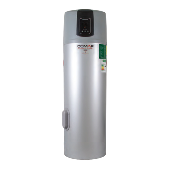
IHP150 INTEGRATED HEAT PUMPS
Please remove all packing materials, MOST IMPORTANTLY those
inside the air-discharge outlet at the top of the unit, prior to
commissioning.
Cold air-discharge ducting (if used or required) should not exceed
2m in total length without an additional extract fan.
Advertisement
Table of Contents

Summary of Contents for Hydratherm IHP150
- Page 1 Owner’s Manual IHP150 INTEGRATED HEAT PUMPS Please remove all packing materials, MOST IMPORTANTLY those inside the air-discharge outlet at the top of the unit, prior to commissioning. Cold air-discharge ducting (if used or required) should not exceed 2m in total length without an additional extract fan.
-
Page 2: Table Of Contents
Contents PREFACE ................3 PRECAUTIONS FOR END-USERS AND INSTALLERS ..4 OVERVIEW OF PRODUCT ..........8 SPECIFICATIONS .............. 9 OPERATIONAL FUNCTIONS OF THE HEAT PUMP ..11 SPATIAL REGULATIONS FOR INSTALLATION ....12 PLUMBING INSTRUCTIONS ........... 13 PLUMBING INSTALLATION DIAGRAM ......16 CONTROL PANEL DIAGRAM .......... -
Page 3: Preface
Neither HydraTherm (Pty) Ltd nor its authorized distributors or resellers will be held liable in the event of damage to property, injury or death as a result of failure to comply with... -
Page 4: Precautions For End-Users And Installers
procedures to be followed in the event of failure or maintenance being required. Operating manuals are updated from time to time and this will be done without notice to existing customers. If you require an updated manual or a copy in event of the loss of the original, please contact Hydra Therm or your authorized reseller. - Page 5 Power to the auxiliary heating element should be provided by a dedicated circuit breaker on the electrical distribution board. Immediately isolate power in the event of detection of excess noise emission or the smell of refrigerant or chemicals or burning components. Never attempt to repair or maintain the unit yourself, always appoint a qualified and manufacturer-approved contractor.
- Page 6 10. The recommended set-point temperature of the product is not more than 55 degrees Celsius for both the heat pump and auxiliary heating element* (*if used). Beware: hot water can cause permanent physical harm. 11. Always test the temperature at the point of use before exposing your entire body to the hot water.
- Page 7 You are also at risk of electric shock in the event of the product operating with the safety covers/panels removed.
-
Page 8: Overview Of Product
OVERVIEW OF PRODUCT CONTROL PANEL AND LCD DISPLAY FRONT VIEW AIR DISCHARGE AIR INLET... -
Page 9: Specifications
SPECIFICATIONS Parameter U.O.M. Value Heating capacity 1.65 Power input 0.45 Co-efficient of Factor performance Running current 2.05 Auxiliary electric element Power supply 220-240VAC/50Hz/1Ph Water tank capacity Litres 149.2 Rated working pressure Number of compressors Compressor design Rotary Refrigerant R134a Refrigerant charge Grams 1100 Discharge pressure... - Page 10 Pipe size Inch ¾ Moisture resistance Nett weight Kilograms Package weight Kilograms Package length Package width Package height 1900 SANS151 rated Litres 125L volume Rated ambient Air 15 C | Inlet 15 C | Outlet 45 conditions Maximum operating ambient temperature DIMENSIONS Overall height 1825mm...
-
Page 11: Operational Functions Of The Heat Pump
OPERATIONAL FUNCTIONS OF THE HEAT PUMP Compressor Start Delay If the product is re-started from a running state the unit will delay the start of the compressor for 3 minutes as a safety precaution Ambient Temperature If the ambient temperature Protection exceeds a safe operating limit the product will automatically... -
Page 12: Spatial Regulations For Installation
SPATIAL REGULATIONS FOR INSTALLATION Maximum duct length: 2m 100mm 100mm... -
Page 13: Plumbing Instructions
PLUMBING INSTRUCTIONS Please note: All instructions for the plumbing of this water heater must be read in conjunction with SANS10254 (as amended) and all plumbing work, including the installation of any and all valves must comply with SANS10254 (as amended). WARNING The temperature and pressure safety (T/P) valve supplied with the water heater must be mounted on the water heater at the... - Page 14 The installation of the pressure control and expansion relief/control valve must comply with SANS10254 and provide for balanced pressure of hot and cold water to each point of use. The drain-cock supplied with this water heater must be installed at the port marked “water inlet.” Water may be drained from the water heater by opening the screw on the drain-cock.
- Page 15 A suitable geyser tray must be installed in compliance with SANS10254. A suitable pipe must be connected to the “condensate drain” port and installed in a continuously downward direction to drain condensate away from the heat pump safely so as to prevent any water damage from occurring.
-
Page 16: Plumbing Installation Diagram
PLUMBING INSTALLATION DIAGRAM Installations must be performed by qualified, PIRB registered plumbers and done in accordance with the current version of SANS 10254 and SANS 10142 and all local by-laws where applicable. E&OE. -
Page 17: Control Panel Diagram
CONTROL PANEL DIAGRAM OPERATING INSTRUCTIONS POWER When mains power is connected and turned on the heat pump display will activate. If the running indicator light is off, the controller is programmed to turn off. Pressing the Power On/Off button once will activate the heat pump and the red light will illuminate indicating the unit is in heating mode. - Page 18 OPERATING MODES The South African version of the product only caters for the energy saving mode identified by a green light. Since the auxiliary heating element can only be activated manually, changing the heat pump operating mode will not have any effect. The only mode of operation is energy saving (heat pump only).
-
Page 19: Troubleshooting And Self-Diagnostics
RESETTING THE HEAT PUMP OVERHEATING PROTECTOR To reset the 75 C motor thermal cut-out, open the “Over heat protector” cover and press the red reset button. The product will then resume normal operation. TROUBLESHOOTING AND SELF-DIAGNOSTICS The product is equipped to display a series of codes on the LCD display depending on the fault occurring. -
Page 21: Service Contact Details
SERVICE CONTACT DETAILS HydraTherm (Pty) Ltd P.O. Box 2722, Clareinch, 7740 Unit 5 The Meat Factory, Corner of Mowbray Road & Pitt Street, Cape Town 7405 TEL 021 593 0529 | EMAIL info@hydratherm.co.za...
Need help?
Do you have a question about the IHP150 and is the answer not in the manual?
Questions and answers