Table of Contents
Advertisement
Advertisement
Table of Contents

Subscribe to Our Youtube Channel
Related Manuals for Nortek Global V5BV-72WMBC

Summary of Contents for Nortek Global V5BV-72WMBC
- Page 1 NORTEK GLOBAL HVAC, LLC DC Inverter VRF Units Owner's Manual Heat Pump V5BV-72WMBC V5BV-96WMBC V5BV-120WMBC Please read this owner’s manual carefully before operation and retain it for future reference Specifications & illustrations subject to change without notice or incurring obligations...
- Page 2 Preface The DC Inverter Multi VRF System, with the most advanced technology in the world, uses eco-friendly refrigerant R410A. For correct installation and operation, please read this manual carefully. WARNING NOTICE: Failure to comply with warning notice could result in property WARNING damage, serious personal injury or death..
-
Page 3: Table Of Contents
Contents 1 Safety Precautions …………………………………………………………1 2 Product Introduction ………………………………………………………..3 2.1 Names of Main Parts ……………………………………………………………….3 2.2 Combinations of Outdoor Units ……………………………………………………3 2.3 Combinations of Indoor and Outdoor Units ………………………………………4 2.4 The Range of Production Working Temperature ………………………………..5 3 Preparation before Installation …………………………………………….6 3.1 Standard Parts ………………………………………………….…………………..6 3.2 Installation Site ……………………………………………………………………..6 3.3 Piping Work Requirements ………………………………………………………11... -
Page 4: Safety Precautions
DC Inverter VRF Units 1 Safety Precautions WARNING (1) Follow this instruction to complete the installation work. Please read this manual carefully before unit startup and service. (2) Wire size of power cord should be sufficient to handle voltage. The damaged power cord and connection wire should be replaced by appropriate size cable. - Page 5 DC Inverter VRF Units (23) Turn power on to the unit 8 hours before startup. Do not disconnect power when you want to stop the unit for a short period of time, i.e. overnight. (24) If refrigerant leakage occurs during installation, please ventilate immediately. Toxic gas will result if the refrigerant gas meets spark or fire.
-
Page 6: Product Introduction
Cooling Capacity 144 / 44.8 168 / 50.4 192 / 55.9 MBH / kW V5BV-72WMBC V5BV-72WMBC V5BV-96WMBC Combine Models + V5BV-72WMBC + V5BV-96WMBC + V5BV-96WMBC Cooling Capacity 216 / 61.5 240 / 67 264 / 78.4 MBH / kW V5BV-72WMBC... -
Page 7: Combinations Of Indoor And Outdoor Units
DC Inverter VRF Units Cooling Capacity 288 / 84 312 / 89.5 336 / 95 MBH / kW V5BV-96WMBC V5BV-96WMBC V5BV-96WMBC Combine Models + V5BV-96WMBC + V5BV-96WMBC + V5BV-120WMBC + V5BV-96WMBC + V5BV-120WMBC + V5BV-120WMBC Cooling Capacity 360 / 100.5 MBH / kW V5BV-120WMBC Combine Models... -
Page 8: The Range Of Production Working Temperature
DC Inverter VRF Units Fig.2 illustrates the combination of the ODU of Modular DC Inverter Multi VRF System and the IDU of Multi VRF System. IDU can be cassette type, one-way cassette type, wall-mounted type, duct type, etc. When any one IDU receives operation signal, ODU will start to work according to the capacity;... -
Page 9: Preparation Before Installation
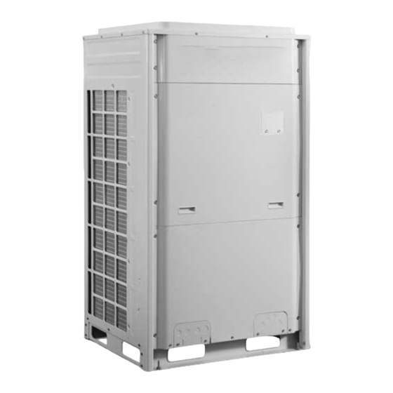
DC Inverter VRF Units 3 Preparation before Installation Note: The graphic is only used for reference. Your product may look differently. Unit: mm(inch). 3.1 Standard Parts Please use the following standard parts supplied with these units. Parts for Outdoor Unit Number Name Picture... - Page 10 DC Inverter VRF Units 3.2.1 When the outdoor unit is totally surrounded by walls, please refer to following figures for clearance dimension. 3.2.1.1 Clearance dimension for single-module unit Fig.3 3.2.1.2 Clearance dimension for dual-module unit Fig.4...
- Page 11 DC Inverter VRF Units 3.2.1.3 Clearance dimension for three-module unit Fig.5 3.2.2 When there is wall (or similar obstruction) above the unit, keep the distance between the unit top and the wall at least 3000mm (10 feet). When the unit is located in a totally open space with no obstructions in four directions, keep the distance between the unit top and wall at least 1500mm (5 feet) (See Fig.6).
- Page 12 DC Inverter VRF Units Fig.6 Fig.7 3.2.3 Space dimension for multiple-module unit For good ventilation, make sure there are no obstructions above the units. When the units are located at a half-open space (front and left/right side is open), install the unit as per these or opposite direction.
- Page 13 DC Inverter VRF Units 3.2.4 Consider seasonal wind direction when installing the outdoor unit Fig.10 3.2.5 Consider snowfall when installing the outdoor unit Fig.11...
-
Page 14: Piping Work Requirements
DC Inverter VRF Units 3.3 Piping Work Requirements Refer to the table below for piping work requirements. R410A Refrigerant System Outer Diameter mm(inch) Wall Thickness mm(inch) Type Φ6.35(1/4) 0.8(1/32) 0.8(1/32) Φ9.52(3/8) 0.8(1/32) Φ12.7 (1/2) Φ15.9(5/8) 1.0(1/32) Φ19.05(3/4) 1.0(1/32) 1/2H 1.2(1/16) Φ22.2(7/8) 1/2H Φ25.4(1) -
Page 15: Installation Instruction
DC Inverter VRF Units 4 Installation Instruction 4.1 Physical Dimension of the Outdoor Unit and Mounting Hole Outline and Physical Dimension of V5BV-72WMBC. Fig.12 Outline and Physical Dimension of V5BV-96WMBC and V5BV-120WMBC unit. Fig.13... -
Page 16: Connection Pipe
DC Inverter VRF Units 4.2 Connection Pipe 4.2.1 Schematic Diagram of Piping Connection Fig.14... - Page 17 DC Inverter VRF Units 4.2.2 Schematic Diagram of Piping Sequence V5BV-72WMBC Fig.15 V5BV-96WMBC and V5BV-120WMBC Fig.16...
- Page 18 DC Inverter VRF Units 4.2.3 Allowable pipe length and drop height between indoor and outdoor units Y type branch joint is used to connect indoor and outdoor units. Connecting method is shown in the figure below. Note: Equivalent length of one Y-type manifold is about 0.5m(1-3/4feet). Fig.17 L10: Length from the first branch to the farthest IDU;...
- Page 19 DC Inverter VRF Units Difference between the pipe length from the first branch of IDU to the farthest IDU and the ≤40(131) L10-L11 pipe length from the first branch of IDU to the nearest IDU Equivalent length from the first branch to the ≤40(131) L6+L7+L8+L9+j furthest piping (1)
- Page 20 DC Inverter VRF Units (4) If the length between an IDU and its nearest branch is above 10m(33 feet), then double the size of the liquid pipe of IDU (only for the pipe size that is≤6.35mm(1/4inch). 4.2.4 Connection Pipe between Outdoor Modules Fig.18 Fig.19 Note: When the distance between outdoor units exceeds 2m (6-1/2 feet), U-type oil trap...
- Page 21 DC Inverter VRF Units Fig.20 Pipe size of basic outdoor module is shown as follows: Pipe between ODU and the first branch of IDU Basic Module Gas Pipe mm(inch) Liquid Pipe mm(inch) V5BV-72WMBC Φ19.05(3/4) Φ9.52(3/8) V5BV-96WMBC Φ22.2(7/8) Φ9.52(3/8) V5BV-120WMBC Φ28.6(1-1/8) Φ12.7(1/2)
- Page 22 DC Inverter VRF Units Pipe between module and branch of ODU Basic Module Gas Pipe mm(inch) Liquid Pipe mm(inch) V5BV-72WMBC Φ19.05(3/4) Φ9.52(3/8) V5BV-96WMBC Φ22.2(7/8) Φ9.52(3/8) V5BV-120WMBC Φ28.6(1-1/8) Φ12.7(1/2) Select the branch of outdoor module Module’s capacity (C) Model Select the branch of outdoor...
- Page 23 4.2.5.4 Fitting pipe between the first manifold from indoor unit and the end manifold from outdoor unit Single module unit Fig.23 Pipe between ODU and the first branch of IDU Cooling Capacity (MBH / kW) Gas Pipe mm(inch) Liquid Pipe mm(inch) V5BV-72WMBC Φ19.05(3/4) Φ9.52(3/8) V5BV-96WMBC Φ22.2(7/8) Φ9.52(3/8) V5BV-120WMBC Φ28.6(1-1/8) Φ12.7(1/2)
- Page 24 DC Inverter VRF Units Fig.24 Cooling Capacity (MBH / kW) Pipe between ODU and the first branch of IDU Gas pipe size mm(inch) Liquid pipe size mm(inch) 144 / 44.8 Φ28.6(1-1/8) Φ12.7(1/2) 168 / 50.4 Φ28.6(1-1/8) Φ15.9(5/8) 192 / 55.9 Φ28.6(1-1/8) Φ15.9(5/8) 216 / 61.5...
- Page 25 DC Inverter VRF Units Fig.25 Total capacity of downstream R410A Refrigerant System Model indoor unit(s) C (MBH) C 68 FQ01A/A 68 C 102 FQ01B/A Y-type Manifold 102 C 239 FQ02/A 239 C FQ03/A 4.2.5.6 Fitting pipe between manifolds Pipe size (between two manifolds at indoor unit side) is based on the total capacity of downstream indoor unit(s).
- Page 26 DC Inverter VRF Units Fig.26 Dimension of the pipe of indoor branch Total capacity of downstream indoor unit(s) C(Btu/h) Gas Pipe mm(inch) Liquid Pipe mm(inch) C 17100 Φ12.7(1/2) Φ6.35(1/4) 17100 C 48500 Φ15.9(5/8) Φ9.52(3/8) 48500 C 75100 Φ19.05(3/4) Φ9.52(3/8) 75100 C 102400 Φ22.2(7/8) Φ9.52(3/8) 102400 C 153500...
-
Page 27: Installation Of The Connection Pipe
DC Inverter VRF Units 4.3 Installation of the Connection Pipe 4.3.1 Precautions when installing the connection pipe (1) Adhere to the following principles during piping connection: Connection pipeline should be as short as possible. The height difference between indoor and outdoor units should be as short as possible. - Page 28 DC Inverter VRF Units Fig.29 (2) Y-type manifold has several pipe sections with different pipe sizes, which matches various copper pipe sizes. Use pipe cutter to cut in the middle of the pipe section with required pipe size and deburr it. See Fig.30. (3) Y-type manifold must be installed vertically or horizontally.
-
Page 29: Air Purging And Refrigerant Charge
DC Inverter VRF Units (3) Thermal insulation for pipeline 1) To avoid condensation or water leakage on connecting pipe, the gas pipe and liquid pipe must be wrapped with thermal insulating material and adhesive tape. 2) For heat pump unit, liquid pipe should withstand at least 70 C (158 ), and gas pipe should withstand at least 120 C(248 ). - Page 30 DC Inverter VRF Units See Fig.33. Fig.32 Fig.33 4.4.2 Additional refrigerant Outdoor unit has been charged with refrigerant before delivery. Charge additional refrigerant for field-installed connecting pipe. If the pipeline is longer than 1m (39 inches), please refer to the following table for charging amount of refrigerant. (Liquid pipe prevails) How much additional refrigerant should be charged? Total refrigerant charging amount R= Pipeline charging amount A + ∑charging amount B of...
-
Page 31: Electric Wiring
IDU/ODU rated capacity collocation ratio C= 48×7/(72+120+120)=108%.The quantity of included IDUs is more than 4 sets. Please refer to the above table. Refrigerant charging amount B for V5BV-72WMBC module is 4.0kg (8.8pounds). Refrigerant charging amount B for V5BV-120WMBC module is 4.0kg (8.8pounds). - Page 32 DC Inverter VRF Units 4.5.2 Wiring of power cord Every unit should have corresponding circuit breaker and overload protection. A main switch is required to control power supply. See Fig.34. Fig.34 Outdoor Unit Minimum Circuit Maximum Overcurrent Power Supply Fuse Capacity Outdoor unit cooling Ampacity Protection...
- Page 33 DC Inverter VRF Units (3) Copper-core cable must be used. (4) The above sectional area is suitable for a maximum distance of 15m (49 feet). If it’s over 15m (49 feet), sectional area must be expanded to prevent overload current from burning the wire or causing fire hazard. (5) Specification of circuit breaker is based on the working condition where the ambient temperature of circuit breaker is 40 C (104 ).
-
Page 34: System Communication
DC Inverter VRF Units Fig. 35 4.6 System Communication 4.6.1 Communication system include: (1) Communication among outdoor basic modules. (2) Communication between ODU and IDU. (3) Communication among IDUs. (4) Communication between IDU and wired controller. (5) Connection between IDU and light board receiver. (6) Communication between different refrigeration systems. - Page 35 DC Inverter VRF Units (7) Graphics of general communication connection. Fig.36 4.6.2 Communication mode of V5 Modular DC Inverter Units CAN bus mode is used for communication between IDU and ODU and communication among IDUs. 4.6.3 Selection and connection mode of V5 communication material 4.6.3.1Select communication material NOTICE! If air conditioners are installed in places where there’s strong electromagnetic interference, the communication wire of IDU and wired controller must ebe shielded, and...
- Page 36 DC Inverter VRF Units (1)Select communication wire between IDU and wired controller Total length of communication line Material type between IDU unit and Wire size Remarks wired controller L m(feet) 1. Total length of communication line can't exceed 250m (820 feet). Light/Ordinary 2.
- Page 37 DC Inverter VRF Units 4.6.3.2 Connection mode of communication (1) All communication wires of V5 must be connected in series. Fig.39 Fig.40...
- Page 38 DC Inverter VRF Units Fig.41 (2) All communication wires of V5 are connected by screws. Fig.42 (3) It is preferred that single communication wires be used. If a single wire is too short, another wire may be welded or pressure welded to it. DO NOT simply twist the wires together. 4.6.4 Communication address Auto addressing technology is used for V5 IDU and ODU.
-
Page 39: Connection Method And Steps For System Communication
DC Inverter VRF Units 4.7 Connection Method and Steps for System Communication 4.7.1 Communication connection between IDU and ODU NOTICE! The centralized controller can be installed as needed. Connect IDU and ODU via terminal D1/D2 of wiring board XT2. Below are the connection graphics for a single unit and for modular units: Fig.43 Connection of single unit... - Page 40 DC Inverter VRF Units Fig.44 Connection of modular unit (1) If there are multiple outdoor modules, then the master unit must be the first outdoor module on the communication wire and should not connect with IDU (master unit is set by SA8 of the outdoor main board).
- Page 41 DC Inverter VRF Units 4.7.2 Communication connection between IDU and wired controller There are 4 kinds of connection between IDU and wired controller, as shown below: Fig.45 One wired controller controls one IDU Fig.46 Two wired controller controls one Fig.47 One wired controller controls multiple IDUs...
- Page 42 DC Inverter VRF Units Fig.48 Two wired controllers control multiple IDUs When two wired controllers control multiple IDUs, the wired controller can be connected to any single IDU, provided that the connected IDU is of the same series. Meanwhile, one and only one of the wired controllers must be set as a slave controller.
- Page 43 DC Inverter VRF Units IDU type Connection wire Main board interface of corresponding IDU Dsp1 (direct to 8-core interface) Duct type IDU Between boards (17-core) Dsp2 (direct to 9-core interface) Fig.49 (1) Wired controller and light board remote receiver can be used at the same time. (2) When light board remote receiver is used, please use remote controller at the same time.
- Page 44 DC Inverter VRF Units Fig.50...
-
Page 45: External Electrical Wiring Diagram
DC Inverter VRF Units 4.8 External Electrical Wiring Diagram Each unit should be equipped with a circuit breaker for short circuit and overload protection., A separate main circuit breaker shall be provided to connect or disconnect power of the entire system. - Page 46 DC Inverter VRF Units 4.8.2 External wiring diagram of modular connection Fig.52 NOTICE! Maximum number of ODU (N) and maximum number of IDU (n) are based on the combination type of ODU. For details, please refer to the introduction of units’ combination.
-
Page 47: Check Items After Installation And Trial Run
DC Inverter VRF Units 5 Check Items after Installation and Trial Run 5.1 Check Items after Installation Check Items Conditions Might Happen Check Has the unit been mounted securely? The unit may fall, vibrate or emit noise. It may cause insufficient cooling/heating Have you done the gas leakage test? capacity. - Page 48 DC Inverter VRF Units (2) Check that all the control wires and cables are connected correctly and safely. Completely open the gas and liquid valves. (3) All the objects like metal filings and debris should be cleared away after installation. (4) Check if the unit and piping system has been damaged due to transportation.
- Page 49 DC Inverter VRF Units Fig.54 (5) Before debugging, make sure the appropriate amount of refrigerant has been added to the pipe (at least 70% of the required refrigerant must be added). (6) Description of each stage of debugging progress: Description of each stage of debugging progress ——...
- Page 50 DC Inverter VRF Units LED3 displays the quantity of IDUs. light light 01~80 blink Confirm the number manually. 04_Confirm the quantity of IDUs System has confirmed the quantity of light light light IDUs. Start next stage. System detects “driven communication light light light...
- Page 51 DC Inverter VRF Units Calculate the refrigerant quantity 11_Calculate manually and confirm it is flowing refrigerant light light light properly (the quantity of refrigerant quantity added into the system must be recorded manually accurately). light light blink Ready for units to start debugging. 12_Confirm debugging Manual calculation of refrigerant...
- Page 52 DC Inverter VRF Units 5.2.2.2 Debugging operation mode V5 multi VRF system has two debugging modes: one is direct operation on main board of outdoor units while the other is PC operation via special software. In PC software debugging, indoor/outdoor parameters can be displayed and historical data can be recorded and queried. (Operation details can be found in software instruction manuals) (1)Debugging through operation on main board of outdoor units In this debugging mode, the following debugging functions are included on the main board:...
- Page 53 DC Inverter VRF Units Step 7: in stage 03, the quantity of modules needs to be confirmed manually. Main board of each module will display: Debugging code Progress code Status code LED1 LED2 LED3 Stage Display Display Display Code Code Code status status...
- Page 54 DC Inverter VRF Units —— Debugging code Progress code Status code LED1 LED2 LED3 Meaning Stage Display Display Display Code code Code status status status 05_Detect internal Light Light Light Detection is finished. Start next stage. communication If error is detected, system will stay at current stage. Error has to be corrrected manually. Below are relevant errors: ——...
- Page 55 DC Inverter VRF Units Elimination methods of above error can be found in Troubleshooting. Step11: stage 07 is “Detect indoor components” If no error is detected, system will display as below and then start next stage. —— Debugging code Progress code Status code LED1 LED2...
- Page 56 DC Inverter VRF Units LED1 LED2 LED3 Stage Display Display Display Code code Code status status status 08_Confirm Preheat time for compressor is less preheated Light Light Light than 8h. compressor Step 13: stage 09 is “Refrigerant check before startup” If the refrigerant quantity meets the requirement of operation startup, system will display as below and start next stage.
- Page 57 DC Inverter VRF Units before startup Check the big and small valves whether they are fully turned on. After the check, press SW6 return button to restart the judgments. If unit detects that valve status is normal, it will display as below and start next stage. ——...
- Page 58 DC Inverter VRF Units Display Display Display Code code Code status status status Debugging is enabled in cooling mode Light Light Light (debugging mode, automatically -selected by system). Error Error occurs during debugging in Light Light Light code cooling mode. Error of other modules occurs during Light Light...
- Page 59 DC Inverter VRF Units display “OF”. Step 19: after debugging is finished, some functions can be set up according to project needs. For specific details, please refer to System Functions Setup. If no special requirements, skip this step. Step 20: deliver the product to user and inform user about usage precautions.
- Page 60 DC Inverter VRF Units 5.2.3 Appendix: judgment reference of normal operational parameters Reference of Debug Parameters of V5 DC Inverter Multi VRF System Debug item Parameter name Unit Reference Outdoor ambient temp ºC(°F) —— Discharge tube temp of ● When system compressor starts up, temp of ºC(°F) inverter compressor 1 discharge tube or casing top in cooling mode is...
- Page 61 DC Inverter VRF Units 1.414=311V. It’s normal if actual voltage varies 15v from the calculated voltage. Operating freq. of Varies from 30Hz to 100Hz inverter compressor 2 Current of inverter According to different operating freq. and different compressor 2 load, current will vary from 7A to 25A. When ambient temp is lower than 35ºC (95°F), IPM IPM temp of inverter ºC(°F)
-
Page 62: Common Malfunction And Troubleshooting
DC Inverter VRF Units 6 Common Malfunction and Troubleshooting Check the following items before contacting for repair. Phenomenon Reason Measure No power supply connected Connect to power supply Voltage is too low Check if the voltage is within rating range The unit doesn’t Broken fuse or breaker trips off Replace fuse or flip breaker switch... - Page 63 DC Inverter VRF Units That's sound of gas refrigerant flow There is sound when unit starts or stops stopping There is slight and continuous sound when That's sound of the drainage system unit is running or after running That’s sound caused by expansion of Cracking sound is heard when unit is panel and other parts due to temperature operating and after turning off...
-
Page 64: Error Indication
DC Inverter VRF Units 7 Error Indication Inquiry method of malfunction display: combine division number and content number to check the corresponding malfunction. For example, division number L and content number 4 together means power supply over-current protection. - Page 65 DC Inverter VRF Units...
-
Page 66: Maintenance And Care
DC Inverter VRF Units 8 Maintenance and Care Maintenance and care should be performed every six months by professional personnel, which will prolong the unit life span. Disconnect the power supply before cleaning and maintenance. 8.1 Outdoor Heat Exchanger Outdoor heat exchanger is required to be cleaned once every six months. Use vacuum cleaner with nylon brush to clean up dust and sundries on the surface of heat exchanger. -
Page 67: After-Sales Service
DC Inverter VRF Units 9 After-sales Service In case the air-conditioning unit you bought has any quality problem or you have any inquiry, please contact the installing technician. Warranty should meet the following requirements: (1) Startup of the unit should be performed by a qualified technician. (2) Only approved accessories can be used on the machine. - Page 68 Specifications & illustrations subject to change without notice or incurring obligations. O’Fallon, MO (12/15) © Nortek Global HVAC, LLC 2015. All Rights Reserved. 547E-1215...
Need help?
Do you have a question about the V5BV-72WMBC and is the answer not in the manual?
Questions and answers