
Summary of Contents for WAVESYS IP-10201LDI
- Page 1 HD IP Fixed Mini Dome Camera User’s Manual_Install Part G Ver. 1.2 / 2021.03 Before installing and using the camera, please read this manual carefully. Be sure to keep it handy for future reference.
-
Page 2: Table Of Contents
Contents INTRODUCTION Important Safety Informa�on Product & Accessories Part Name INSTALLATION Disassemble the Camera Installa�on Installa�on using Mount Bolt & Nut Adjus�ng the Camera angle Cabling SPECIFICATION Dimension... - Page 3 Safety Instruction These instruc�ons are intended to ensure that the user can use the product correctly to avoid danger or property loss. If the product is not func�oning properly or damaged, contact the service center or purchasing office. Warnings Cautions Serious injury or death may be caused Injury or equipment damage may be caused if any of these warnings are neglected.
- Page 4 Installa�on and Use Precau�ons The ba�ery (ba�ery pack or equipped ba�ery) must not be exposed to excessive heat such as sunlight, fire, etc. Do not disassemble the camera at your discre�on. If you forcefully install the product with excessive force, malfunc�on can damage the camera. Do not punch or shake the camera and be careful not to damage the camera with careless storage or malfunc�on.
- Page 5 Disposal of Old Appliances 1. The symbol marked in the product, will follow and covered by the Europe Direc�ve 2002/95/EC. 2. All electornic disposal of waste is differenct by the government or locally, so so it need to check. 3. The correct disposal of your old appliance will help prevent poten�al nega�ve consequences for the environment and human health.
-
Page 6: Product & Accessories
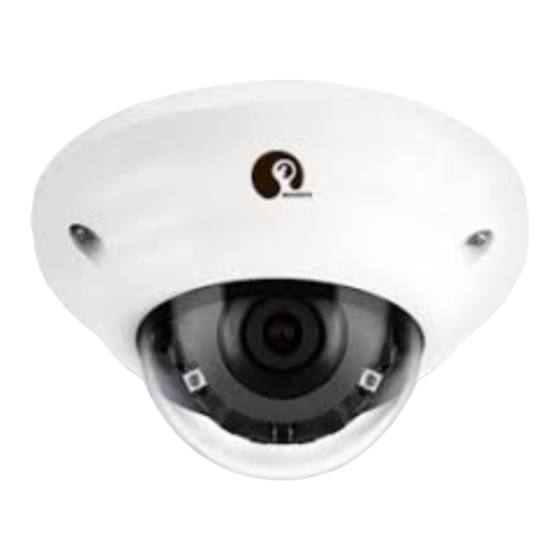
Introduc�on - Product & Accessories Camera Cables Mount Bolt & Nut Torx Wrench Waterproof cap & Gasket Screw & Template Sheet Quick Manual Plas�c Anchor-2pcs for Installing by Bolt & Nut... -
Page 7: Part Name
Introduc�on - Part Name Dome Cover Lens IR Switch IR LED Gimbal Reset Bu�on Bo�om Case DC Power Jack RJ-45 Connector Waterproof cap... -
Page 8: Disassemble The Camera
Installa�on - Disassemble the camera Before installing your camera, you have to read the following cau�ons. 1. You have to check whether the loca�on can bear five �mes of the weight of your camera. 2. Don’t let the cable to be caught in improper place or the electric line cover to be damaged. Otherwise it may cause a breakdown or fire. -
Page 9: Installa�On
Installa�on - Installa�on Template Sheet Disassemble the camera. See the sec�on ‘Installa�on - Disassemble the camera’ for details. Using the template sheet, make the cabling hole on the wall/ceiling. Connect the network cable and power cable respec�vely. See the sec�on 'Installa�on - Cabling' for details. -
Page 10: Installa�On Using Mount Bolt & Nut
Installa�on - Installa�on Using Mount Bolt & Nut Template Sheet Disassemble the camera. See the sec�on ‘Installa�on - Disassemble the camera’ for details. Using the template sheet, make the cabling holes on the ceiling panel. Insert the 2 mount bolts into bo�om case of camera. - Page 11 Installa�on - Installa�on Using Mount Bolt & Nut Insert the mount bolts into template holes a�er connec�ng the cable. Fix the bo�om case by �ghtening mount nuts to mount bolts on the ceiling panel. To achieve desired view direc�on and orienta�on, rotate 3-axis gimbal.
-
Page 12: Adjus�Ng The Camera Angle
Installa�on - Adjus�ng the Camera angle Panning 355° Rota�on 360° Til�ng 60°... -
Page 13: Cabling
Installa�on - Cabling Two Op�ons Use a PoE-enabled switch to connect data and power through a single cable and begin viewing and recording images instantly. A non-PoE switch will require an adaptor for power transmission. 1. Using a PoE-Enabled Switch 2. -
Page 14: Dimension
Specifica�ons - Dimension Unit: mm 28.5 32.5 ø105...
Need help?
Do you have a question about the IP-10201LDI and is the answer not in the manual?
Questions and answers