Table of Contents
Advertisement
Advertisement
Table of Contents

Subscribe to Our Youtube Channel
Summary of Contents for Eltek Valere PSR327
- Page 1 RECTIFIER PSR327 USER MANUAL UM_PSR327_21TE_E_R5.0...
- Page 2 ELTEK VALERE DEUTSCHLAND GmbH GB Industrial Schillerstraße 16 D-32052 Herford + 49 (0) 5221 1708-210 + 49 (0) 5221 1708-222 Email Info.industrial@eltekvalere.com Internet http://www.eltekvalere.com 2009. ELTEK VALERE DEUTSCHLAND GmbH. All rights reserved. ©2009. ELTEK VALERE DEUTSCHLAND GmbH. UM_PSR327_21TE_ E_R5.0...
- Page 3 Section 4.2.1 “Start-up behaviour” inserted; Technical 2009-04-29 specifications: Adjustable output voltage range changed. Section 4.5 “Monitoring” reworked. 2009-05-15 Minor text modifications, section 4.7 “Default value setting 2009-07-07 for NiCd batteries” inserted. Technical specifications: “Internal decoupling circuit” 2009-07-24 corrected. ©2009. ELTEK VALERE DEUTSCHLAND GmbH. UM_PSR327_21TE_ E_R5.0...
-
Page 4: Table Of Contents
Figure 3) Front view................................8 Figure 4) Male connectors ..............................9 Figure 5) Module air flow..............................10 Figure 6) Output power diagram (example PSR327/48-56) ................... 12 Figure 7) Screenshot “Special software for CAN-Dongle”..................14 Figure 8) Module dimensions ............................19 ©2009. ELTEK VALERE DEUTSCHLAND GmbH. -
Page 5: Safety Instructions And Waste Disposal Rules
The above statement from EU directive 2002/96/EC applies to all electric modules installed within EU countries. In countries outside the EU, different rules may apply regarding waste disposal of electric modules. For more information about waste disposal of your discarded equipment, contact your ELTEK VALERE DEUTSCHLAND partner. ©2009. ELTEK VALERE DEUTSCHLAND GmbH. UM_PSR327_21TE_ E_R5.0... -
Page 6: General Information
The PSR327 rectifier rectifies sinusoidal AC input voltage to DC output voltage. The PSR327 is a hot plug-in module with rear side connectors and is designed to be mounted in an assembly set 19’’ sub rack (see section 3.2). Due to the state-of-the-art circuitry design, the unit has very low losses and therefore very compact dimensions, low weight and high power density. -
Page 7: Available Options And Assembly Equipment
Page 7 (20) 3.2 Available Options and Assembly Equipment Designation Material Code DC Power Rack DCR PSR327-8.1 LV (assembly set 19’’ sub rack 3U incl. backplane for three PSR327/48V or 60V rectifiers and one 102-327-318.LV01 UPC3-48/60V DC controller), DCC-CB1 connection board included. -
Page 8: Front View/Front Side Led Panel
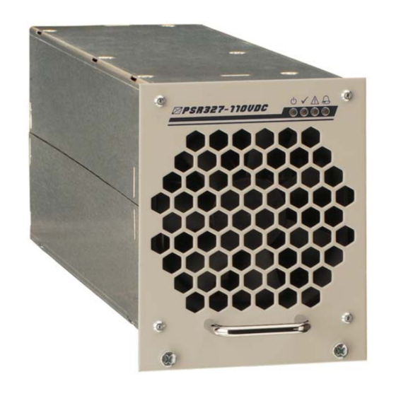
Rectifier PSR327 User Manual Page 8 (20) 3.3 Front view/Front side LED panel The PSR327 rectifier is equipped with the following four LED indicators: INPUT OK OUTPUT OK Vout> ALARM For more information about the LED indicators, see section 4.4... -
Page 9: Rear Side Connection
- - - Hardwarecoding CODE2 Hardwarecoding CODE1 Collective Alarm NC Collective Alarm COM Collective Alarm NO - - - - - - (+) output voltage sense link (-) Output (-) Output (+) Output (+) Output ©2009. ELTEK VALERE DEUTSCHLAND GmbH. UM_PSR327_21TE_ E_R5.0... -
Page 10: Cooling And Air Flow Direction
Figure 5) Module air flow 3.6 Communication Interface The PSR327 rectifier is equipped with a serial data interface in accordance with the Controller Area Network (CAN) specification. The CAN-Bus connection is integrated in the rear side connector. Several modules in a system or parallel connection can be controlled and monitored through the CAN- Bus by a central UPC3 DC controller unit. -
Page 11: Handling
6. Secure the module using the two captive screws (M3x12) provided with the module. 7. Switch ON the module by external MCB. Note: The PSR327 is serially equipped with an internal output side decoupling diode. This ensures hot plug-in capability for the module and enables the operator to add modules under operating conditions. -
Page 12: Charge Characteristic/Output Power Diagram
Page 12 (20) 4.3 Charge Characteristic/Output Power Diagram The charge characteristic of the PSR327 is a power limited IV characteristic curve in accordance with DIN 41772/DIN 41773. For modules in parallel operation mode a load sharing of about ±10% is attained due to a sloping output voltage line (-1% at 100% Inom). -
Page 13: Led Indications
3 seconds. After 30 seconds the Short circuit circuit operation by the output voltage module automatically tries to restart value. (criteria: Vout ≤83% of Vnom) repeatedly. *For factory set output voltage threshold values, see section 4.6 ©2009. ELTEK VALERE DEUTSCHLAND GmbH. UM_PSR327_21TE_ E_R5.0... -
Page 14: Threshold & Default Values
But when the CAN-Bus connection is inactive for more than five seconds (e. g. due to trouble), the PSR327 automatically switches back to the internally stored default values. In this case it is ensured that the battery is charged in the float charge mode. -
Page 15: External Functions
Attention! Dust combined with moisture or water may influence or destroy the internal electronic circuits. Dust inside the unit can be blown out with dry compressed air. The interval between the checks depends on ambient conditions of the installed module. ©2009. ELTEK VALERE DEUTSCHLAND GmbH. UM_PSR327_21TE_ E_R5.0... -
Page 16: Troubleshooting
No output Is mains voltage present? Check voltage Mains switched to “ON” position? Check PSR327 module plugged in securely? Check Incorrect polarity or short circuit at the output? Check LED V> on? 1.) Switch the module off and on. 2.) Check the settings for V>... -
Page 17: Technical Specifications
CCITT-A ≤ 1.8mV ≤2.0mV Dynamic accuracy of the <3% Vnom at load changes between 10%-90%-10% Inom; charge voltage transient time ≤1.5ms Short circuit protection Continuously short circuit proof; 1 x Inom ©2009. ELTEK VALERE DEUTSCHLAND GmbH. UM_PSR327_21TE_ E_R5.0... - Page 18 Front panel: RAL 7035, neutral, black print RAL 9005 Compliances: CE conformity Compliance to safety EN60950-1; VDE0100 T410; VDE0110; EN50178; EN60146 standards Compliance to EMC standards EN55022/24 (ITE), class “A“; EN61000-4 T2-5 ©2009. ELTEK VALERE DEUTSCHLAND GmbH. UM_PSR327_21TE_ E_R5.0...
-
Page 19: Dimensional Drawings
Rectifier PSR327 User Manual Page 19 (20) 8.1 Dimensional Drawings Figure 8) Module dimensions ©2009. ELTEK VALERE DEUTSCHLAND GmbH. UM_PSR327_21TE_ E_R5.0... - Page 20 Supplier: ELTEK VALERE DEUTSCHLAND GmbH GB Industrial Schillerstraße 16 D-32052 Herford + 49 (0) 5221 1708-210 + 49 (0) 5221 1708-222 Email Info.industrial@eltekvalere.com Internet http://www.eltekvalere.com 2009. ELTEK VALERE DEUTSCHLAND GmbH. All rights reserved.
Need help?
Do you have a question about the PSR327 and is the answer not in the manual?
Questions and answers