Table of Contents
Advertisement
Quick Links
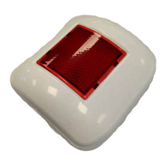
GENERAL DESCRIPTION
The WIL0010 remote indicator is an output device which, activated by the control panel, switches on its red light in the event of an emergency
fire alarm. It is battery powered and doesn't need any system cabling installation.
The activation command is sent from the control panel to the indicator through the wire to wireless translator interface module and other
possible wireless expander modules. It is intended to be used within the FireVibes range of products.
Picture 1
DEPLOYMENT PROCEDURE
1) Select a location for the remote indicator. See LOCATION SELECTION.
2) Unbox the remote indicator from its packaging.
3) Power up the remote indicator. See POWERING UP - FIRST TIME USE / POWERING UP - RECOVERY.
4) Link the remote indicator to the system. See LINKING - WAKE-UP / LINKING - ONE-BY-ONE.
5) Install the back cover. See FIXING THE BACK COVER.
6) Install the device onto the back cover. See HOW TO REMOVE AND REINSTALL THE FRONT COVER.
7) Test the remote indicator. See TESTING.
LOCATION SELECTION
Select a location for the remote indicator that conforms to your local applicable safety standards and that is in a good posi tion for sending /
receiving wireless signals to / from the father EWT100, IWT100 or XWT100 network device.
It is advisable to use the EWT100-TESTER
survey kit to locate a good wireless installation
Mount the remote indicator as far as possible from metal objects, metal doors, metal window openings, etc. as well as cable conductors,
cables (especially from computers), otherwise the operating distance may greatly drop.
The WIL0010 must NOT be installed near electronic devices and computer equipment that can interfere with its wireless communication
quality.
INIM ELECTRONICS S.R.L. VIA DEI LAVORATORI 10, FRAZIONE CENTOBUCHI, 63076 MONTEPRANDONE, ITALY
WIL0010
Wireless Remote indicator
Battery B
housing
Tamper
switch
Link program
switch
Battery A
housing
LED INDICATOR STATUS MESSAGES
The LED indicator communicates to the final user the status of the WIL0010 .
Device status
LEDs indication
Power up (DIP on "ON")
Blinks red 4 times
Power up (DIP opposite "ON")
Blinks green 4 times
Entering wake-up mode
Blinks alternatively green / red 4 times
Link success (one-by-one)
Blinks green 4 times, then the same pattern again
Link failure (one-by-one)
Enters wake-up mode and signals "Entering wake-up mode" following this failure
Link success (wake-up)
Blinks green 4 times, then same pattern again
Link failure (wake-up)
Blinks green 4 times, then blinks red on once, then blinks alternatively green / red 4 times
Normal condition
LED off (can be programmed so as to blink green every wireless communication)
Alarm activation
Red LED steady on
Battery fault
LED off (can be programmed so as to blink amber every 5 seconds)
Tamper fault
LED off (can be programmed so as to blink amber every 5 seconds)
Replaced
Blinks green 4 times
POWERING UP AND LINKING - PRELIMINARY NOTES
TW-RI-01 needs to be powered up with the supplied batteries.
Linking is the operation through which WIL0010 is "wirelessly connected" to a EWT100, IWT100 or XWT100 FireVibes network device.
POWERING UP - FIRST TIME USE
Use this procedure the first time you power up a WIL0010 .
1) Make sure the Link / program switch is set on "ON".
2) Insert the two supplied batteries into their device's lodgments.
Ensure that the batteries are installed properly, with their polarities matching the indications on the device.
POWERING UP - DEVICE LINKED TO THE SYSTEM
Use this procedure when a WIL0010 is successfully linked to its FireVibes system and you have to extract one or both batteries (e.g. batteries
substitution).
1) Reinsert the battery or both batteries into their lodgments.
Do not touch the Link / program switch.
If performing a batteries substitution, use two brand new batteries and substitute both of them.
Ensure that the batteries are installed properly, with their polarities matching the indications on the device.
POWERING UP - RECOVERY
Use this procedure when you fail to link successfully a WIL0010 or you want to link it again.
1) Move alternatively the Link / program switch 5 times.
2) Set the Link / program switch on "ON".
3) Insert the two supplied batteries into their device's lodgments.
Ensure that the batteries are installed properly, with their polarities matching the indications on the device.
LINKING - WAKE-UP
"Wake-up" linking consists in associating one or more child devices to the FireVibes system altogether in a single operation.
Wake-up is performed either through the FireVibes Studio software or the EWT100 / IWT100 keyboard-screen interface; it CANNOT be done
through XWT100 devices.
1) Create the "virtual model" (be aware that the Output Module type has to be selected to link a remote indicator) of the WIL0010 either on
FireVides Studio or on the EWT100 / IWT100.
2) Power-up the remote indicator (either "first time use" or "recovery").
3) Set the Link / program switch OPPOSITE to "ON".
4) Trigger the wake-up procedure either from FireVibes Studio or from the EWT100 / IWT100.
5) Wait the end of the "wake-up" linking procedure.
6) Check on FireVibes Studio or from EWT100 / IWT100 for linking success. Consult their user manual.
info@inim.biz
Please mind that LED signalling burns out bat-
tery power, therefore reducing batteries lifespan.
Table 1
DCMIINE0WIL0010-110
2
Advertisement
Table of Contents

Summary of Contents for INIM Electronics FireVibes WIL0010
- Page 1 5) Wait the end of the “wake-up” linking procedure. 6) Check on FireVibes Studio or from EWT100 / IWT100 for linking success. Consult their user manual. INIM ELECTRONICS S.R.L. VIA DEI LAVORATORI 10, FRAZIONE CENTOBUCHI, 63076 MONTEPRANDONE, ITALY info@inim.biz DCMIINE0WIL0010-110...
- Page 2 Full details on our warranty and product’s returns policy can be obtained upon request. RESET To reset the wireless remote indicator from alarm it is necessary to reset the system from the control panel: alarm indication will deactivate. INIM ELECTRONICS S.R.L. VIA DEI LAVORATORI 10, FRAZIONE CENTOBUCHI, 63076 MONTEPRANDONE, ITALY www.inim.biz info@inim.biz...
Need help?
Do you have a question about the FireVibes WIL0010 and is the answer not in the manual?
Questions and answers