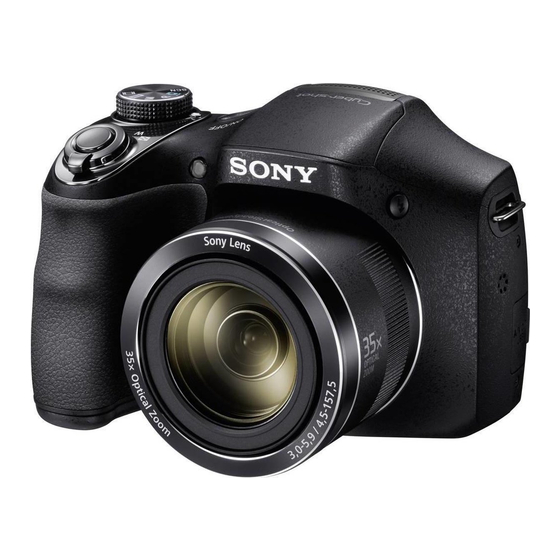
Sony DSC-H300 Service Manual
Hide thumbs
Also See for DSC-H300:
- User manual (487 pages) ,
- Instruction manual (203 pages) ,
- User manual (180 pages)
Table of Contents
Advertisement
Quick Links
SERVICE MANUAL
Ver. 1.0 2013.09
Internal memory
Internal memory
ON BOARD
ON BOARD
SERVICE NOTE (Check the following note before the service.)
1-1. METHOD FOR COPYING OR ERASING THE DATA IN INTERNAL MEMORY
1-2. DEDICATED A/V CABLE (OPTIONAL ACCESSORY)
1-3. REGARDING FUSE
The components identified
Les composants identifiés par
by mark 0 or dotted line with
une marque 0 sont critiques
mark 0 are critical for safety.
pour la sécurité.
Replace only with part number
Ne les remplacer que par une
specified.
pièce portant le numéro spécifié.
DSC-H300
9-834-755-11
DSC-H300
US Model
Canadian Model
AEP Model
UK Model
Russian Model
E Model
Chinese Model
Brazilian Model
DIGITAL STILL CAMERA
Sony Corporation
Revision History
Ver.
Date
History
1.0
2013.09
Official Release
983475511.pdf
S.M. Rev.
Contents
issued
—
—
2013I08-1
© 2013.09
Published by Sony Techno Create Corporation
Advertisement
Table of Contents

Summary of Contents for Sony DSC-H300
- Page 1 0 sont critiques mark 0 are critical for safety. pour la sécurité. Replace only with part number Ne les remplacer que par une specified. pièce portant le numéro spécifié. 2013I08-1 DSC-H300 © 2013.09 Sony Corporation 9-834-755-11 Published by Sony Techno Create Corporation...
-
Page 2: Specifications
DIAGRAMMES SCHÉMATIQUES ET LA LISTE DES PIÈCES SONT Model information table ARE CRITICAL TO SAFE OPERATION. REPLACE THESE COMPO- CRITIQUES POUR LA SÉCURITÉ DE FONCTIONNEMENT. NE REM- NENTS WITH SONY PARTS WHOSE PART NUMBERS APPEAR AS PLACER CES COMPOSANTS QUE PAR DES PIÈCES SONY DONT Model DSC-H300 SHOWN IN THIS MANUAL OR IN SUPPLEMENTS PUBLISHED BY LES NUMÉROS SONT DONNÉS DANS CE MANUEL OU DANS LES... -
Page 3: Service Note
Note that formatting permanently erases all data including even protected images. 1-2. DEDICATED A/V CABLE (OPTIONAL ACCESSORY) Dedicated A/V cable is not supplied with this model. For details of the dedicated A/V cable, refer to the “ACCESSORIES” page. DSC-H300 1-1E... -
Page 4: Repair Parts List
CND : Canadian model RU : Russian model Left View Front View 4 Main Board Assy 2 LCD Back View Right View Bottom View 5 Lens Section 1 Rear Cover Assy Link DISCHARGING OF THE CHARGING CAPACITOR ACCESSORIES ASSEMBLY DSC-H300... -
Page 5: Operation Notes
If you pull on the wires, they might be broken. • The proper way to connect a connector is to grab the connector instead of the wires. If you push on the wires, they might be broken. DSC-H300... -
Page 6: Exploded Views
Left View Bottom View Right View Main Board Section (See page 2-4) (Claws) (Claws) Ref. No. Part No. Description Ref. No. Part No. Description 4-488-395-01 BUTTON, FUNCTION 4-488-403-01 SCREW_TP_1.7_4.5_BLK_AB 4-488-396-01 BUTTON, CONTROL 4-447-230-01 SCREW, M1.7X3 X-2588-849-1 COVER ASSY, REAR DSC-H300... -
Page 7: Main Board Section
Ref. No. Part No. Description Ref. No. Part No. Description A-1989-698-A MAIN BOARD ASSY (Note) 4-488-403-01 SCREW_TP_1.7_4.5_BLK_AB A-1989-699-A LCD MODULE 4-488-402-01 SCREW_TP_1.7_4.0_SVR_AB Soldering position 1-576-415-11 FUSE, MICRO (1608 TYPE) (2A/32V) Black Soldering position 1-576-415-11 FUSE, MICRO (1608 TYPE) (2A/32V) DSC-H300... - Page 8 LENS BLOCK ASSY (Note 2, 3) 4-447-160-01 DAMPER, LENS 4-488-393-01 OPTICAL FILTER BLOCK (Note 1) 4-488-399-01 SPONGE, LENS CUSHION 4-488-394-01 CCD RUBBER A-1989-700-A CCD BLOCK ASSY 4-488-402-01 SCREW_TP_1.7_4.0_SVR_AB 4-447-142-01 BASE PLATE, TRIPOD 4-447-230-01 SCREW, M1.7X3 4-488-404-01 SCREW_TP_1.7_5.5_SVR_AB 4-274-002-01 SCREW_TP_1.4_3_SVR_AB DSC-H300...
- Page 9 #S2 X 4 → Open the BT Lid (1) → #S1 X 3 Back View Bottom View Main Frame Section (See page 2-7) Ref. No. Part No. Description Ref. No. Part No. Description X-2588-845-1 LENS HOLDER 4-488-403-01 SCREW_TP_1.7_4.5_BLK_AB X-2588-848-1 COVER ASSY, FRONT 4-488-402-01 SCREW_TP_1.7_4.0_SVR_AB 4-488-388-01 COVER, USB 4-447-225-01 SCREW, TP1.4X6 SVR DSC-H300...
-
Page 10: Main Frame Section
FRAME ASSY, BATT CHAMBER A-1989-735-A SPEAKER ASSY X-2588-882-1 FRAME ASSY, MAIN X-2588-844-1 LID ASSY, BATT 4-488-389-01 SHAFT, BATT LID 4-488-402-01 SCREW_TP_1.7_4.0_SVR_AB 4-488-400-01 COVER, DC 4-488-391-01 EYELET(G), STRAP 4-488-398-01 COVER(G), EYELET X-2586-053-1 MICROPHONE ASSY A-1989-733-A BOARD ASSY, AF ASSIST LIGHT (Note) DSC-H300... - Page 11 BLOCK ASSY, RL FPC X-2588-863-1 BASE ASSY, RL DIAL A-1989-702-A BOARD ASSY, DETECT SW (Note) A-1989-704-A ST BOARD ASSY (Note) A-1989-708-A BASE ASSY, FLASH (Note) 4-488-392-01 FPC BOARD, ST CONNECTION 4-447-165-01 DIFFUSION PANEL 4-488-401-01 BUTTON, POWER 4-488-403-01 SCREW_TP_1.7_4.5_BLK_AB 4-488-402-01 SCREW_TP_1.7_4.0_SVR_AB 4-273-597-01 SCREW_TP_1.4_3.5_SVR_AB DSC-H300...
- Page 12 - You can access the URL of the support site described in the Instruction Manual. This item is supplied with the unit as an accessory, but is not prepared as a service part. Ref. No. Part No. Description (Not supplied) LR6 (size AA) alkaline batteries DSC-H300 2-9E...
- Page 13 • Side view Assembly-2: Routing harnesses (Top cover section) not reflected. The red belt is seen. • IR cut coating surface Lens Device side The red coating is reflected. Harnesses of Harnesses of the Flash Unit the Detect SW Board DSC-H300 3-1E...
-
Page 14: Overall Block Diagram
4. BLOCK DIAGRAMS 4-1. OVERALL BLOCK DIAGRAM DSC-H300 4-1E...


Need help?
Do you have a question about the DSC-H300 and is the answer not in the manual?
Questions and answers