Table of Contents
Advertisement
Quick Links
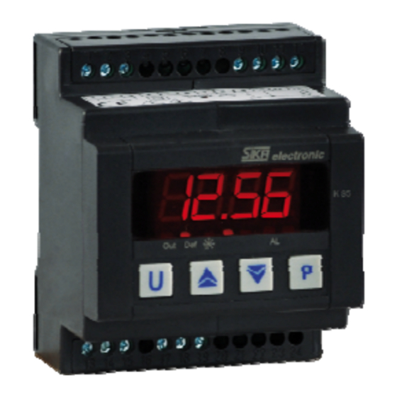
CONTROLLER AND
MINI-PROGRAMMER
Engineering Manual
Code : ISTR-MK85ENG07 - Vr. 0.7 (ENG)
1. OUTLINE DIMENSIONS (mm)
70
1
2 3 4 5 6 7 8 9 10 11 12
K 85
T un
Out1 Out2
-
=
+
Out3
13 14 15 16 17 18 19 20 21 22 23 24
2. CONNECTION DIAGRAM
DIG
In1
S U P P LY
1
2
3
4
R ela y s O U T 1 ,2 : 8A -A C 1 (3 A -A C 3 ) / 25 0 V
R ela y O U T 3 : 5 A -A C 1 (2A -A C 3 ) / 2 5 0 V
S S R
R E LAY S
N O
N C
1 3 14 15
1 6 1 7 1 8 1 9 2 0 2 1 2 2 2 3 2 4
O U T 1
K85
27
21
Prg
0 ..5 0 /6 0 m V, 0 . .1 V
0 /1 ..5 V , 0 /2 ..1 0 V
0 /4 ..2 0 m A
A C T I V E
4 ..2 0 m A
A C T IV E
e x t.
g e n .
4 ..2 0 m A
PA S S IV E
(2 w i re s )
DIG
In2
A
B
G N D
5
6
7
8
9
1 0 11
D I G . IN
R S 4 8 5
S S R : 2 0 m A / 1 0 V D C
C
C
N O
C
N O
O U T 3
O U T 2
SIKA - K series - ENGINEERING MANUAL -V0.7 PAGE 1
This instrument is intended for permanent installation, for
indoor use only, in an electrical panel which encloses the
rear housing, exposed terminals and wiring on the back.
Select a mounting location having the following
characteristics:
1) it should be easily accessible
2) there is minimum vibrations and no impact
3) there are no corrosive gases.
4) there are no water or other fluid (i.e. condensation).
5) the ambient temperature is in accordance with the
operative temperature (from 0 to 50 °C).
6) the relative humidity is in accordance with the
instrument specifications ( 20% to 85 %).
The instrument can be mounted on OMEGA rail in
accordance with EN 50 022 (35 x 7.5 mm or 35 x 15
mm) regulations.
2.2 GENERAL NOTES ABOUT INPUT WIRING
1) Don't run input wires together with power cables.
2) External components (like zener barriers, etc.)
connected between sensor and input terminals may
cause errors in measurement due to excessive and/or
not balanced line resistance or possible leakage
currents.
3) When a shielded cable is used, it should be
12
connected at one point only.
4) Pay attention to the line resistance; a high line
resistance may cause measurement errors.
2.3 THERMOCOUPLE INPUT
_
11
+
12
Fig. 3 Thermocouple input wiring
External resistance: 100 Ω max, maximum error 0,5 %
of span.
Cold junction: automatic compensation from 0 to 50 °C.
Cold junction accuracy : 0.1 °C/°C after a warm-up of
20 minutes
Input impedance: > 1 MΩ
Calibration: according to EN 60584-1.
NOTE: for TC wiring use proper compensating cable
preferable shielded.
O U T 1 0 V D C
(M a x 2 0 m A )
P T C
N T C
2.4 INFRARED SENSOR INPUT
P t 10 0
_
T C
11
1 2
I N P U T
+
12
Fig. 4 Infrared input wiring
External resistance: don't care condition.
N C
Cold junction: automatic compensation from 0 to 50 °C.
Exergen
Advertisement
Table of Contents

Related Manuals for SIKA K85


Summary of Contents for SIKA K85
- Page 1 1 6 1 7 1 8 1 9 2 0 2 1 2 2 2 3 2 4 Cold junction: automatic compensation from 0 to 50 °C. O U T 1 O U T 3 O U T 2 SIKA - K series - ENGINEERING MANUAL -V0.7 PAGE 1 ...
-
Page 2: Thermistor Input
Accuracy : 0.5 % of Span + 1 dgt @ 25 °C. Protection: NOT protected from short circuit. Internal auxiliary PWS: 10 V DC (+ 10%), 20 mA max. SIKA - K series - ENGINEERING MANUAL -V0.7 PAGE 2 ... -
Page 3: Serial Interface
2.11 SERIAL INTERFACE Please, provide a T type 1A, 250 V fuse externally. A/A’ A/A’ B/B’ 8 B/B’ C/C’ A/A’ 8 B/B’ SIKA - K series - ENGINEERING MANUAL -V0.7 PAGE 3 ... -
Page 4: Technical Characteristics
Operating temperature: from 0 to 50°C (from 32 to 122°F). Storage temperature: -30 to +70°C (-22 to 158°F) Humidity: from 20 % to 85% RH, non condensing. Protections:WATCH DOG (hardware/software) for the automatic restart. SIKA - K series - ENGINEERING MANUAL -V0.7 PAGE 4 ... -
Page 5: Configuration Procedure
- The display will show alternately the measured value and the message <<St.bY>> or <<od>>. The instrument is in configuration mode. - The instrument does not perform any control (the SIKA - K series - ENGINEERING MANUAL -V0.7 PAGE 1 ... - Page 6 In the following pages we will describe all the parameters the following change: of the instrument. However, the instrument will only show [3] dP [129] ES.L = -1999 [130] ES.H = 9999 SIKA - K series - ENGINEERING MANUAL -V0.7 PAGE 2 ...
- Page 7 [8] inE - Selection of the Sensor Out of Range type = Program Hold [transition] that will enable the safety output value. The first closure allows to hold program Available: Always execution and a second closure continue SIKA - K series - ENGINEERING MANUAL -V0.7 PAGE 3 ...
- Page 8 P.End = Program end indicator = Program Run/Hold [status] P.HLd = Program hold indicator When the contact is closed the program is P. uit = Program wait indicator running. SIKA - K series - ENGINEERING MANUAL -V0.7 PAGE 4 ...
- Page 9 = Out-of-range or burn out indicator nonE = Output not used. With this setting the status P.FAL = Power failure indicator of the this output can be driven directly SIKA - K series - ENGINEERING MANUAL -V0.7 PAGE 5 ...
- Page 10 LHAb LHd E Range: 0 to 15 with the following rule. +1 = Alarm 1 +2 = Alarm 2 +4 = Alarm 3 +8 = loop break alarm SIKA - K series - ENGINEERING MANUAL -V0.7 PAGE 6 ...
- Page 11 Alarm threshold value and the point the Alarm only by an external command (U button, digital inputs automatically resets. or serial link). - When the alarm threshold plus or minus the SIKA - K series - ENGINEERING MANUAL -V0.7 PAGE 7 ...
- Page 12 When no output is programmed as control output = alarm 2 enabled during Stand by mode nonE = Alarm not used LoAb = Absolute low alarm HiAb = Absolute high alarm LHAb = Absolute band alarm SIKA - K series - ENGINEERING MANUAL -V0.7 PAGE 8 ...
- Page 13 Deviation low alarm (relative) start. Available: when [48] LbAt is different from oFF - [40] AL3t = LidE Deviation high alarm (relative) Range: from [42] AL3L to [43] AL3H engineering units. SIKA - K series - ENGINEERING MANUAL -V0.7 PAGE 9 ...
- Page 14 OUT H.rE G at every power up (heating) = Not used OUT c.rEG = Fast auto tuning with automatic restart at (cooling) every power up SIKA - K series - ENGINEERING MANUAL -V0.7 PAGE 10 ...
- Page 15 - oFF - derivative action excluded from 20,0 to 130.0 seconds - from 1 to 9999 seconds when [62] H.Act = SLou Note: auto-tune functions calculate this value. from 40,0 to 130.0 second SIKA - K series - ENGINEERING MANUAL -V0.7 PAGE 11 ...
- Page 16 [71] SS.tH – Threshold for soft start disabling instrument starts with an integral action equal to zero. Available: When at list one output is programmed as control output. SIKA - K series - ENGINEERING MANUAL -V0.7 PAGE 12 ...
- Page 17 PErc = The value coming from serial will be scaled [75] SP 1 - Set Point 1 Available: When at least one output is programmed as control output. Range: from [73] SPLL to [74] SPHL engineering units SIKA - K series - ENGINEERING MANUAL -V0.7 PAGE 13 ...
- Page 18 Available: When at list one output is e programmed as control output. Range: 0.01 ÷ 99.99 units per minute = ramp disabled (step transfer) General note about remote set point: when the SIKA - K series - ENGINEERING MANUAL -V0.7 PAGE 14 ...
- Page 19 Note: this parameter allows to manage timer execution U.dG.d = Start at RUN command detection with a first by a parameter (without digital inputs or U button). step in stand by SIKA - K series - ENGINEERING MANUAL -V0.7 PAGE 15 ...
- Page 20 When you use for example 2 groups only, it is sufficient - inF = Step transfer to set the set point of the third group equal to OFF. The instrument will mask all the following parameters of the SIKA - K series - ENGINEERING MANUAL -V0.7 PAGE 16 ...
- Page 21 - rES = Program reset Range: from OFF to 9999 engineering units Note: this parameter allows to manage program execution by a parameter. Note: for more details see [96]Pr.b1 parameter SIKA - K series - ENGINEERING MANUAL -V0.7 PAGE 17 ...
- Page 22 (longer than 10 second) resets the timer. At the end of the counting, the instrument will show “t.End” messages alternately with the measured value. SIKA - K series - ENGINEERING MANUAL -V0.7 PAGE 18 ...
- Page 23 = Not used must be set to “AS.Pr”. = Instantaneous power (kW) If the “[120]dSPu” parameter is different from = Power consumption (kW/h) “AS.Pr” The memorization function will be hinibit. SIKA - K series - ENGINEERING MANUAL -V0.7 PAGE 19 ...
- Page 24 Another important step of the instrument configuration is Range: from -300 to 300 Engineering Units due to the possibility to create a custom HMI (interface) in order to make the instrument easy to SIKA - K series - ENGINEERING MANUAL -V0.7 PAGE 20 ...
- Page 25 - Int - - SPAt - SPAt - dEr - - AL1 - - Aut.r - A 10 Aut.r ...... Now, proceed as follows: SIKA - K series - ENGINEERING MANUAL -V0.7 PAGE 21 ...
-
Page 26: Operative Modes
10 seconds. b) All parameter modification are protected by a time out. If no button is pressed for more than 10 second the instrument comes automatically back to the SIKA - K series - ENGINEERING MANUAL -V0.7 PAGE 22 ... -
Page 27: Automatic Mode
running the instrument will show the segment Shutter currently performed and the Event status as shown below: where the first character can be “r” for a SIKA - K series - ENGINEERING MANUAL -V0.7 PAGE 23 ... -
Page 28: Manual Mode
- When the instrument is swapped from stand by to auto Dig In 1 Time modes, the instrument will start automatically the alarm masking, and the soft start functions. SIKA - K series - ENGINEERING MANUAL -V0.7 PAGE 24 ... -
Page 29: Error Messages
sending the instrument to our company. The faulty product must be shipped to SIKA with a NOTE: When an over-range or an under-range is detailed description of the faults found, without any fees detected, the alarms operate as in presence of the... - Page 30 SIKA Dr. Siebert und Kühn GmbH & Co. KG Struthweg 7-9 34260 Kaufungen TEL.: +49 5605 803-0 FAX: +49 5605 803-54 internet : www.sika.net email: info@sika.net SIKA - K series - ENGINEERING MANUAL -V0.7 PAGE 26 ...
- Page 31 Appendix A InP group Para Vis. n° Description Dec. Range Def. meter Promo. HcFG Parameter available by serial link. TC/RTD Accord Not vis It shows the current hardware TC/PTC ing to Current Voltage Hardw. ...
- Page 32 Para Vis. n° Description Dec. Range Def. meter Promo. 14 = Program run/reset 15 = Instrument in Manual mode 16 = Sequential set point selection 17 = SP1 / SP2 selection 18 = Set point Binary selection 19 = Digital inputs in parallel to the UP and Down keys...
- Page 33 Para Vis. n° Description Dec. Range Def. meter Promo. o2Ac Out 2 action dir = Direct action rEU = Reverse action dir.r = Direct with reversed LED ReU.r = Reverse with reversed LED Out 3 function NonE = Output not used A-22 H.rEG = Heating output...
- Page 34 AL1 group Para n° Description Dec. Range Def. meter Promo. AL1t Alarm 1 type nonE = Alarm not used LoAb LoAb A-47 = Absolute low alarm HiAb = Absolute high alarm LHAb = Absolute band alarm LodE = Deviation low alarm (relative) HidE = Deviation high alarm (relative) LHdE = Relative band alarm...
- Page 35 AL3 group Para n° Description Dec. Range Def. meter Promo. AL3t Alarm 3 type nonE = Alarm not used LoAb nonE = Absolute low alarm HiAb = Absolute high alarm LHAb = Absolute band alarm LodE = Deviation low alarm (relative) HidE = Deviation high alarm (relative) LHdE = Relative band alarm...
- Page 36 Para n° Description Dec. Range Def. meter Promo. Auto Autotuning selection -4 = Oscillating auto-tune with automatic restart at power up and after all set point change -3 = Oscillating auto-tune with manual start -2 = Oscillating auto-tune with auto-matic start at the first power up only -1 = Oscillating auto-tune with auto-matic restart at...
- Page 37 Para Vis. n° Description Dec. Range Def. meter Promo. SP.rt Remote set point type RSP = The value coming from serial link is used as trin remote set point trin = The value will be added to the local set point selected by SPAt and the sum becomes the operative set point PErc = The value will be scaled on the input range and...
- Page 38 Para Vis. n° Description Dec. Range Def. meter Promo. Pr.E1 Events of the first group From 00.00 to 11.11 00.00 Pr.S2 Set point of the second soak OFF or from SPLL to SPHL A-78 Pr.G2 Gradient of the second ramp From 0.1 to 1000.0 (inF= Step transfer)
- Page 39 Para Vis. n° Description Dec. Range Def. meter Promo. diSP Display management nonE = Standard display nonE A-95 Pou = Power output SPF = Final set point Spo = Operative set point AL1 = Alarm 1 threshold AL2 = Alarm 2 threshold AL3 = Alarm 3 threshold Pr.tu = Program time up Pr.td...
- Page 40 From -300 to 300 (E.U.) A-10 A.H.P Adjust High Point From A.L.P +10 ÷to 9999 (E.U.) 9999 A-11 A.H.o Adjust High Offset From -300 to 300 (E.U.) A-12 SIKA - K series - ENGINEERING MANUAL -Vr. 0.6 PAGE A.10 ...
Need help?
Do you have a question about the K85 and is the answer not in the manual?
Questions and answers