Table of Contents
Advertisement
Quick Links
Advertisement
Table of Contents

Related Manuals for CCi PiMPro Smart Series

Summary of Contents for CCi PiMPro Smart Series
- Page 1 PiMPro Smart Series User Guide PiMPro Smart Series User Guide Document Date: October 27, 2021 Latest Update: January 6, 2023 Document Authors: John Baszak, CCI, Applications Engineering & Technical Support © Copyright 2023 CCI Revision 1.0 Page 1 of 64...
-
Page 2: Table Of Contents
Status Indications When Charging the PiMPro Smart Series PIM Analyzer Battery is Fully Charged ..........60 2.9.5 Status Indications When an Error Occurs in Charging the PiMPro Smart Series PIM Analyzer Battery ..........60 2.10 PiMPro Smart Series PIM Analyzer Battery Usage ............................ 60 2.10.1... - Page 3 GSM 900 (PiMPro Smart Series 900) 890 - 915 925 - 937.5 (TX1), 951.5 - 980 (TX2) DCS 1800 / UMTS 2100 (PiMPro Smart Series Dual Band 1821) 1710 - 1785 (RX1), 1920 - 1980 (RX2) 1805 - 1837 (TX1), 1855 - 1880 (TX2)
-
Page 4: Introduction
Smart Series exhibits an exceptional -176 dBc PIM measurement sensitivity. 1.1.2 Technical Assistance For Technical Assistance in the use of the PiMPro Smart Series PIM Analyzer please contact CCI (Communication Components, Inc.) at the following address and phone numbers: 89 Leuning Street South Hackensack, NJ 07606 Phone Number: 201-342-3338 (9:00 A.M. -
Page 5: Important Information
1.4 Product Overview Specifications for the PiMPro Smart Series PIM Analyzer can be found in Table 1 of this manual. The section below provides a brief product overview and block diagram of the PiMPro Smart Series PIM Analyzer. -
Page 6: Construction And Layout
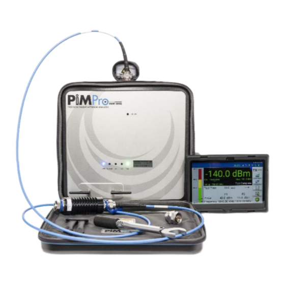
PiMPro Smart Series PIM Analyzer. Figure 1 shows an overall view of the PiMPro Smart Series PIM Analyzer with locations of the Status LED’s (PWR, ALARM, TX, RX, WiFi), the WiFi Antenna and the small LCD for unit status (Date, Time, Battery Charge, PA (Power Amplifier) Temperature, plus any alarm messages will be displayed here). - Page 7 Figure 3 – Power, Ethernet, Battery, USB and Other Connections Access 1.4.2.1 “RF ON” Indicator An “RF ON” (Red LED) indicator is located near the top of the PiMPro Smart Series PIM Analyzer as shown in Figure 1 above. 1.4.2.2 Status LED’s There are five (5) Status LEDs located on the main panel of the PiMPro Smart Series PIM Analyzer as shown in Figure 1.
- Page 8 1.4.2.7 DC Input from AC Adapter The 28VDC Input from the AC Adapter is located on the right-hand side of the PiMPro Smart Series PIM Analyzer between the ON/OFF Power Switch and the External Clock Input when facing the PiMPro Smart Series PIM Analyzer.
-
Page 9: Functional And Physical Specifications
+46 dBm (40 Watts)) when the "TX ON" RED LED is ON. 1.4.3 Functional and Physical Specifications Electrical and mechanical specifications for the CCI PiMPro Smart Series product line can be found in Table 1. 1.4.4 Equipment Changes CCI reserves the right to make changes to the equipment, including but not necessarily limited to component substitution and circuitry changes. -
Page 10: Pimpro Smart Series Operation
2.3 Open the PiMPro Smart Series Once the user has verified that the WiFi connection to the PiMPro Smart Series has been established, find the PiMPro icon shown in figure 6 (the icon will list PiMPro and a version number (in this case 1.06.30 is shown)) on the tablet screen and click on it to get to the PiMPro Smart Series Main screen. -
Page 11: Pimpro Smart Series Main Menu
2.4 PiMPro Smart Series Main Menu The PiMPro Smart Series Main Menu will appear as shown in figure 7 below. It will contain the icons noted below. 1) A toolbar is found at the top of the PiMPro Smart Series Main Menu window, and it contains the following items (from left to right): a. -
Page 12: Select Pim And R.loss Icon
PiMPro Smart Series User Guide 2.4.2 Select PIM and R.Loss Icon Press the PIM and R.Loss icon found in the Main Menu screen on the tablet shown in Figure 7. This will open PIM and R.Loss screen on the tablet as shown in Figure 8 below. A listing of the available or viewable items on this screen and a brief description follow: 1) IM Bar Chart - indicates upper, pass, fail and lower IM limits in dBm. - Page 13 “OFF” setting. Now the user can loosen and disconnect the Low PIM High Power Termination. Connect the RF Cable (System, Feeder or other) to be tested to the RF Output of the CCI PiMPro Smart Series Analyzer, be sure to terminate the cable with the high power PIM Load. Ensure that the connectors are all “clean”...
- Page 14 2.4.2.4 Record Measurement The PiMPro Smart Series PIM Analyzer will display the current PIM readings of the feeder or device it is connected to. When you are ready to record the reading being displayed (Note: the PIM readings should be stable before recording the measurement – consult the PiMPro Smart Series User Manual for...
- Page 15 Label and Comment pop-up window is displayed as shown in Figure 12. The PiMPro Smart Series PIM Analyzer does provide a list of default labels as shown in Figure 12. Additionally, the user can click on “Add Label” to open a keyboard entry screen which the user can then use to type the desired label. The “Menu”...
- Page 16 PiMPro Smart Series User Guide 2.4.2.7 Select Label Menu Sector (Cont.) Figure 12 - Select Label Window 2.4.2.7.1 Comment Comment bar allows for extra information to be added to further update whatever information the “User” feels is necessary. Pressing the comment bar will open the Keyboard Entry Screen. For instance, the comment can indicate that this is a “return to the site...”...
- Page 17 PiMPro Smart Series User Guide 2.4.2.7.6 GPS Status GPS Status can be determined by depressing the GPS Status Icon. This opens the GPS Status pop-up window (see figure 13). If no data is available, the screen will appear as shown in figure 14.
- Page 18 PiMPro Smart Series User Guide 2.4.2.9 Show Graph The Show Graph function (see figure 15 below) allows the user to view the Instantaneous PIM & Return Loss vs. Time in a graph format as an alternative to viewing the instantaneous data, along with the Maximum and Minimum data points.
- Page 19 PiMPro Smart Series User Guide 2.4.2.10 Load/Save Setup Pressing the Load/Save Setup icon from any measurement screen allows the user to load a Setups are a “description” of the measurement previously saved setup, save a modified setup. function, power levels and frequency settings, and can be saved in the PIM Analyzer Disk or to the USB.
- Page 20 PiMPro Smart Series User Guide 2.4.2.10.5 Copy Setup Allows the user to copy the desired setup to/from the Local Drive/USB Drive as desired. 2.4.2.10.6 Delete Setup Allows the user to delete an unwanted setup. 2.4.2.11 Configure PIM Limit Levels Pressing the PIM Scale on the touch screen display opens the...
- Page 21 “Extended” Mode per instruction below. Selection of one of the Battery Life radio buttons as shown in figure 17 allows selection as follows: 1) Low Noise – allows for “Low Noise” operation of the PiMPro Smart Series PIM Analyzer (Transmitter sampling time 64 msec).
- Page 22 PiMPro Smart Series User Guide 2.4.2.11.6 Pressing the OK icon on the touch screen display accepts any changes that have been made to any of the selections available on the “Configure PIM Scale” pop-up window. 2.4.2.12 IM Reading The IM Reading is the largest font size numeric value on the...
- Page 23 Tone 2 Frequency windows have a keypad and allows for entry of the appropriate frequency in MHz as shown in figure 21. Note that this example lists the values for the PiMPro Smart Series PIM Analyzer 1821. Figure 21 -...
- Page 24 PiMPro Smart Series User Guide testing. Figure 22 - IM Select Window, (IM3) @ F1 = 1810.0 MHz and F2 = 1870.0 MHz 2.4.2.17 RF OFF/ON When the RF is “OFF” the RF Indicator (slider next to TX) text will appear with a...
-
Page 25: Rx Interference
PiMPro Smart Series User Guide 2.4.3 RX Interference icon will open the “RSSI vs Frequency” window. This is a new Pressing the RX Interference test function that looks for external interference in the Rx band. The test works by keeping the transmitter(s) (amplifier(s)) off and sweeping the receiver across the entire Rx band. -
Page 26: Frequency Sweep
PiMPro Smart Series User Guide 2.4.4 Frequency Sweep icon will open the “Frequency Sweep” function window. This is a test Pressing the Frequency Sweep function that takes PIM measurements through one sweep across the band. The test works by keeping the first transmit tone fixed while moving the other. - Page 27 PiMPro Smart Series User Guide 2.4.4.5 Graph Markers and Delta Measurements All graphical measurements (RSSI, Frequency Sweep, and PiMPoint) can now be further processed to set two markers. The analyzer will automatically calculate and display the difference (delta) between the two markers. Marker placement is simplified with a variety of “marker helpers”...
- Page 28 PiMPro Smart Series User Guide 2.4.4.5.3 Display and Delta Calculation The top of the display will show the “1” and “2” marker levels and frequencies in “Green” text. The calculated “Delta” will appear below the “1” and “2” as “d” and will list the delta in level (dBm or dBc), and the delta in frequency in “White”...
-
Page 29: Das Test
Pressing the DAS Test icon in the Main Menu will open the “DAS Test” function window (see figure 28). Two methods of DAS Testing are available on the PiMPro Smart Series units. The DAS TX test is used to inject a single tone signal into a DAS System at low power for extended periods of time. - Page 30 PiMPro Smart Series User Guide 2.4.5.1.1 Tone Frequency Pressing the Tone Frequency bar will open the Set tone Frequency pop-up window. This allows the user to set the TX frequency within the frequency range shown in the pop-up window. This will be similar to the F1/F2 Frequency Set Window shown in figure 22 and described in paragraph 2.4.2.14.
- Page 31 RX Frequency allows the user to set the RX Frequency over the specified limits (1710.0 - 1785.0 MHz & 1920 – 1980 MHz for the PiMPro Smart Series 1821) to be sampled during the RX “Capture” test. The frequency setting is similar to the Tone 1 and Tone 2 frequency setting previously shown in this manual.
- Page 32 PiMPro Smart Series User Guide 2.4.5.2.2 Show Graph Note that “Show Graph” in the RX “Capture” test is basically the same as the “Display View,” except that the representation is Graphical, rather than a listing of values on the screen. See figure 31 below for an example of this Show Graph test.
-
Page 33: Pimpoint
Using the accessory kit's -80 dBm PIM Standard at the chosen reference plane and terminating the PIM Standard with the CCI Low PIM Load allows for the analyzer to store calibration parameters which become the reference PIM magnitude and phase from which all further measurements are calculated. During this calibration process, it is imperative to have clean connectors as well as applying proper torque to all connections before pressing the "CAL"... - Page 34 PiMPro Smart Series User Guide 1. Calibration Parameters. Various calibration parameters can be set by the user as seen in the PIMPoint Details Window shown in figure 33 below. a. Selection of DTP or DTF. The user can select whether to measure the Distance to PIM (DTP), Distance to Fault (DTF), or both parameters.
- Page 35 PiMPro Smart Series User Guide 2.4.6.1 Initiate PIMPoint Press the PIMPoint icon in the Main Menu widow. This will open the widow shown in figure 34 below. Figure 34 – PIMPoint Window 2.4.6.1.1 Select IM Order Only the 3 order IM is allowed to be utilized for DTP test.
- Page 36 PiMPro Smart Series User Guide 2.4.6.1.3 “Select Cable” Being Used The user can select the “Default” RF Cable with settings of Velocity Ratio at 88%, and Loss per 100 ft. (dB) set to 3.0 dB. If other cable characteristics are desired, the user can select another cable as shown in the selection list which opens when the “bar”...
- Page 37 “Please Connect PIM Standard” Warning Window 2.4.6.2.3 Calibration with PIM (50 ohm) Load Disconnect the PIM Standard from the PiMPro Smart Series PIM Analyzer, and then connect the “Please Connect 50 ohm Load” pop-up window Low PIM (50 ohm) Load to the PiMPro output. The is already present as shown in figure 38 below.
- Page 38 40 below. Pressing “OK” in the pop-up window initiate the calibration process. The PiMPro Smart Series PIM Analyzer will start taking data points and will show a “progress bar” at the bottom of the screen. Depress “Abort...
- Page 39 Perform the PIMPoint measurement of the Feedline by depressing the Start Sweep icon in the PIMPoint window. The PiMPro Smart Series PIM Analyzer will start taking data points and will show a “progress bar” at the bottom of the screen. When the test run is complete the trace will indicate where the highest PIM reading has been measured.
-
Page 40: Cable Loss Measurement
The ability to measure Insertion Loss of a cable of any length by specifying the cable type has been added to the PiMPro Smart Series PIM Analyzer. To measure the insertion loss, cables can be left OPEN (unterminated), or can be terminated with a SHORT. - Page 41 2.4.7.2 Connect Feed-Line to be Measured Connect the Feed-Line (which is connected to an Antenna) to be measured to the RF Output of the PiMPro Smart Series PIM Analyzer. Hand-tighten the Feed-Line and then use a torque wrench to properly torque the connector.
-
Page 42: Configure System
PiMPro Smart Series User Guide 2.4.8 Configure System Pressing the Configure System icon on the touch screen display Main Menu opens the System Configuration window (see figure 46). The configuration items available to view or modify include the following: 1) Set Clock... - Page 43 PiMPro Smart Series User Guide 2.4.8.3 Manage Labels By depressing the Manage Labels icon on the System Configuration window, the Manage Labels window opens (see figure 47). This window (Menu) allows the user to Add, Edit or Delete labels to the window.
- Page 44 PiMPro Smart Series User Guide 2.4.8.4 Manage Cables The user can select the “Default” RF Cable with settings of Velocity Ratio at 88%, and Loss per 100 ft. (dB) set to 3.0 dB. If other characteristics are desired, the user can select another cable as shown in the selection list which opens when the “bar”...
- Page 45 PiMPro Smart Series User Guide 2.4.8.4.3 Edit Cable Information If it is desired to change existing cable by adding information to or removing information from the existing cable name, or to change errors in the Relative Propagation Velocity or Loss per...
- Page 46 Install Version icon shown in figure 50 installs the version of S/W which the user has selected. Once the installation of the S/W is complete a reboot of the PiMPro Smart Series will occur. 2.4.8.5.2 Delete Version Selecting the Software Version to be deleted and depressing the...
- Page 47 PiMPro Smart Series User Guide 2.4.8.6 Manage Resources Pressing the Manage Resources Icon in the Main Menu opens the Manage System Resources window as seen in figure 51 below. The following items are available from this window: 1) Report Files (memory used by report files)
- Page 48 Clear Old S/W allows the user to delete any old versions of S/W that are loaded in the memory of the PiMPro Smart Series. While keeping old S/W Versions allows the user to be able to revert to a former version which is known to function properly, performing “Clear Old S/W”...
- Page 49 PiMPro Smart Series User Guide 2.4.8.9 PiMPro Ethernet Manager Please note that the PiMPro Ethernet Manager has been added for future development, and that the PiMPro cannot be controlled via the Ethernet at this time. Pressing the “PiMPro Ethernet Manager”...
-
Page 50: Reports
PiMPro Smart Series User Guide 2.4.9 Reports icon on the Main Menu window opens the “Follows the Report” window shown in Pressing the Reports figure 55. Depressing the Manage Reports icon opens the Manage Reports Listing and Menu shown in figure 56. - Page 51 PiMPro Smart Series User Guide 2.4.9.1 View Report Pressing the View Report icon on the Report Listing window (after highlighting a report to be viewed) opens the Active PDF test report file, a portion of which is shown in figure 57.
- Page 52 Pressing the Edit Report Icon brings you to a window such as shown in figure 59 below, and it is available in PiMPro Smart Series. This feature is used to allow changes to be made during and after measurements, as well as to make changes to a saved report without throwing away any of the original data taken.
- Page 53 PiMPro Smart Series User Guide 2.4.9.2.2 Edit Sector/Feeder Information The Site Information can be edited by pressing on the “Sector/Feeder” information shown in blue text. Pressing this will open the screen shown in figure 61. Pressing on the sector or feeder line will open the keyboard and the user can than modify the sector or feeder information as needed.
- Page 54 PiMPro Smart Series User Guide 2.4.9.2.4 Expand/Contract Pressing the Plus or Minus icons on the left side of the tablet screen allows the user to Expand or Contract the information shown in the Edit Report window. 2.4.9.2.5 View Report The individual test data or graph can be viewed in PDF format by pressing the “eye” icon to the right of the test listing on the tablet screen.
- Page 55 PiMPro Smart Series User Guide 2.4.9.3 Copy Report icon on the Report Listing window in figure 56 will open “Report Not Pressing the Copy Report Selected Please Select Report” pop-up window (see figure 64) if the report to be copied has not been already selected.
- Page 56 PiMPro Smart Series User Guide 2.4.9.4 Rename Report icon on the Report Listing window in figure 56 will open “Report Not Pressing the Rename Report Selected Please Select Report” pop-up window (see figure 66) if the report to be copied has not been already selected.
-
Page 57: Manage Snapshots
PiMPro Smart Series User Guide 2.4.9.5 Delete Report icon on the Report Listing window in figure 56 will open “Report Not Pressing the Delete Report Selected Please Select Report” pop-up window (see figure 67) if the report to be copied has not been already selected. -
Page 58: Update Of Pimpro Smart Series Software
PiMPro Smart Series User Guide 2.5 Update of PiMPro Smart Series Software Ensure that the PiMPro Smart Series PIM Analyzer Software is up to date. To ensure that the software is up to date perform the steps listed in paragraphs 2.5.1 through 2.5.8 below. -
Page 59: Autosave
68 for an example of the Autosave pop-up window after powering the PiMPro Smart Series PIM Analyzer. Please note that the Autosave screen will be seen at PiMPro Smart Series turn-on, especially after a power failure or a session where the user did not save data. -
Page 60: Status Indications When Charging The Pimpro Smart Series Pim Analyzer Battery
2.9.5 Status Indications When an Error Occurs in Charging the PiMPro Smart Series PIM Analyzer Battery The Battery Charger LED will blink Red when an error occurs during the charging of the PiMPro Smart Series PIM Analyzer Battery. Possible reasons for the error include: 1) Battery is Fully Charged. -
Page 61: Lithium Polymer Rechargeable Battery Care And Precautions
1) Handle the Lithium Polymer Battery with extreme care: Dropping the battery can result in permanent damage 2) Remove the battery from the PiMPro’s battery slot prior to shipping the PiMPro Smart Series PIM Analyzer PIM Analyzer. 3) Use only CCI specified charger or PiMPro Smart Series PIM Analyzer Internal charging feature to recharge the battery. -
Page 62: Inspection And Maintenance
2) Fans/Fan Covers c. The fans/fan covers in the PiMPro Smart Series should be kept clean to insure proper air flow through the PiMPro Smart Series. The fans/fan covers can be wiped clean, and a vacuum cleaner can also be used for cleaning. -
Page 63: C Appendix C -Declarations Of Conformity
PiMPro Smart Series User Guide C Appendix C –Declarations of Conformity CE Declaration of Conformity Hereby, Communication Components Inc. 89 Leuning Street South Hackensack, NJ 07606 USA declares that the following products are in compliance with the essential requirements of Directive 2014/30/EU (EMC Directive) and Directive 2014/35/EU (LVD Directive) if installed and operated in accordance with manufacturer’s instructions, per Certificate of Compliance No. - Page 64 PiMPro Smart Series User Guide Revision History Date Revision Author Changes Released 1/6/2023 J. Baszak Release PiMPro Smart Series User Manual © Copyright 2023 CCI Revision 1.0 Page 64 of 64 ™...
Need help?
Do you have a question about the PiMPro Smart Series and is the answer not in the manual?
Questions and answers