Table of Contents
Advertisement
Quick Links
Advertisement
Table of Contents

Related Manuals for Dill 1504-572

Summary of Contents for Dill 1504-572
- Page 1 Thank you for purchasing the Dill TPMS Trailer Kit. Properly inflated tires in- crease fuel economy, reduce tire wear, and increase handling. A warning sys- tem to notify you of an underinflated tire will help give you time to respond prior...
-
Page 2: Table Of Contents
Table of Content Page 1. System Overview: 1.1 System Components 1.2 How the System Works 1.3 Display indicators and Controls 1.4 Transmitter Components 1.5 Position of Transmitter and ID Module 3. Transmitter Installation: 3. Using TPMS Unit: 3.1 Getting Started 3.2 Transmitter Activation Cold Inflation Pressure Setting 3.4 Restore Default Setting... -
Page 3: System Overview
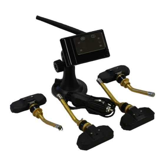
1. System Overview As a vehicle safety device, the TPMS trailer kit monitors tire pressure and tem- perature. It will provide warnings about abnormal conditions such as low pressure, high pressure, and high temperature. 1.1 System Components OPTIONAL ANTENNA DASHBOARD DISC 12V DC POW- ER CORD &... -
Page 4: Display Indicators And Controls
1.3 Display Indicators and Controls PRESSURE TEMPERATURE UNIT UNIT RIGHT FRONT TIRE ABNORMAL ICON RIGHT REAR TIRE CYCLE BUTTON LEFT REAR TIRE LEFT FRONT TIRE ANTENNA SET KEY CHIP IDENTIFIER LOCATION FOR TRANSMITTERS RESTORE KEY 1.4 Transmitter Components ELECTRONIC TRANSMITTER VALVE STEM RATCHET BODY... -
Page 5: Position Of Transmitter And Id Module
1.5 Position of Transmitter and ID module Note the default installation position of the transmitter and ID modules as illus- trated. A letter identifier marked on the transmitter, id module, and hex nut is shown on each component. The letters “LF/RF/LR/RR” on the back of the display unit correspond to the tires‟... - Page 6 2.2 Install the valve stem assembly via ratchet body into the transmit- Transmitter ter. Slide the body into the trans- mitter. Verify the teeth from the ratchet body is opposite from the transmitter teeth. 2.3 Insert the valve stem through the Ratchet rim hole and verify that the rubber Body...
-
Page 7: Using Tpms Unit
2.10 Apply suds on the valve tip, grommet / rim seal. If no leakage is found, in- stall the valve cap. Otherwise, re-inspect and resolve leak issue. 2.11 Dynamically balance the wheel before it is put back on the vehicle. 2.12 Use the same procedures to install the other three sensors. -
Page 8: Transmitter Activation
An immediate audible “Beep” sound will indicate the display unit is on. In 2 to 3 minutes, the display unit will show the tire pressures in yellow, along with four blue tire position lights. 3.2 Transmitter Activation Note: reference section 2 for transmitter installation. The transmitters are shipped in “sleep”... -
Page 9: Normal Monitoring
3.5 Normal Monitoring 3.5.1 Stationary State: The transmitter will detect tire pressures and temperatures at 8- second intervals and transmit the data to the display at 2-minute inter- vals as long as they are normal. As the data is received, the display will refresh. -
Page 10: Tire Rotation
A replacement transmitter and id module can be purchased from a Dill distribu- tor or retailer, list available at www.trailertpms.com. Note: When requesting a replacement of the damaged transmitter, order the same letter identifier (reference 1.5). -
Page 11: Replace Transmitter And Id Module
Interchange ID chip module A and ID chip module C. Reactivate the system (reference section 3.2) to accept new transmit- ter positions and to indicate the proper location of the transmitter on the display unit. 3.8 Replacement of Transmitter and ID Module Verify a “System Malfunction (reference section 3.6.4)”... -
Page 12: Specifications
4. Specifications 4.1 Transmitter Weight: 1.25 oz. (35g) Dimensions: 0.59” x 2.50” x 1.11” (1.5 x 2.8 x 6.4 cm) Operating Temperature Range: -40°F to 257°F (-40°C to 125°C) Pressure Accuracy: ±2PSI (±.14Bar) Temperature Accuracy: ±5.4°F (±3°C) ...
Need help?
Do you have a question about the 1504-572 and is the answer not in the manual?
Questions and answers