Table of Contents
Advertisement
Quick Links
Advertisement
Table of Contents

Subscribe to Our Youtube Channel
Summary of Contents for Hologic Diagenode Bioruptor Pico
- Page 1 Bioruptor Pico ® Sonication System Version 2 11.2022...
- Page 2 Guarantee Limited one year global warranty Diagenode guarantees all products from any manufacturing defects as we rigorously test all products to meet strict quality standards. Diagenode warrants that all standard components of its instruments will be free of defects in materials and workmanship for a period of one (1) year from the date that the warranty period begins, unless the original quotation or accompanying documentation states a different warranty period.
-
Page 3: Table Of Contents
Contents BIORUPTOR PICO ® Critical steps for maintenanceand efficient shearing Introduction Technical specifications Equipment installation Installation Tube holders & tubes BIORUPTOR COOLER ® Safety Design and functions Operation Maintenance Disposal Technical data... - Page 4 PICO MANUAL BIORUPTOR ®...
-
Page 5: Bioruptor ® Pico
BIORUPTOR PICO ®... -
Page 7: Critical Steps For Maintenanceand Efficient Shearing
Critical steps for maintenance and efficient shearing General warnings • DO NOT turn on the instrument without water. • DO NOT tilt the Bioruptor Pico. To change the water, use either the plastic pump or a beaker (be careful ® not to scratch the bottom of the sonicaton bath). -
Page 8: Introduction
Introduction Diagenode’s Bioruptor Pico uses a gentle method of sonication to retain the integrity of ® DNA and/or biological complexes, including chromatin, protein-protein binding, protein- DNA complexes and other biochemical and biological assay systems. The Bioruptor Pico ® sonication system uses a sonication bath to generate indirect sonication waves, which emanate from an ultrasound element below the water tank. -
Page 9: Technical Specifications
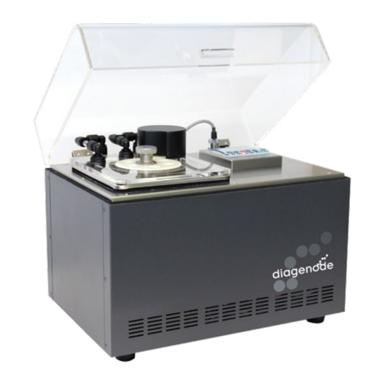
Bioruptor Pico technical specifications ® BIORUPTOR PICO ® Power supply 100-230V, 50/60Hz, 2.1A (EU) / 4.2A (US) Ultrasonic wave frequency 20-60 kHz Ultrasonic wave output power 25-210 W Sonication unit dimensions 350 (W) x 245 (D) x 280 (H) mm Sonication bath volume 750 ml Timer... - Page 10 Getting to know your Bioruptor Pico system ® Bioruptor Pico components overview ® Sonication bath Motorized lid Sonication unit Power cable (EU) Power cable (US) Tube holder Bioruptor Cooler ® PICO MANUAL BIORUPTOR ®...
- Page 11 Sonication bath The sonication bath is a critical component of the instrument. The generators below the tank produce ultrasonic waves which are then transferred through water. The sonication bath requires special handling and care as described below. Handling The sonication unit must remain upright at all times, especially when moved. Tilting the sonication unit or handling roughly may damage the ultrasound emitter component, resulting in a substantial drop in sonication efficiency.
- Page 12 maintain a constant water level in the tank. The integrated regulating valve ensures that water will only be replaced during the off cycle to avoid any interference between the water flow and the sonication process. Bioruptor Cooler ® Sonication unit Motorized lid The motorized lid, along with the gear plate accessory, keeps the sample tubes in constant rotation and ensures optimal position in the sonication...
-
Page 13: Equipment Installation
Equipment installation The following pages contain information on installing your particular Bioruptor Pico model. ® This equipment must only be installed by personnel after reading this section. Consider all hazards even though no particular hazards have been identified during installation. Before starting installation work, turn the main switch off and secure the unit against being re-energized. - Page 14 Installing the Bioruptor Pico system ® Before starting the installation, turn the main switches off and make sure that the unit is not plugged into an electrical outlet. 1. Open the boxes and unpack all components Bioruptor Pico Bioruptor Cooler ®...
- Page 15 Controlling the sonication Digital Timer: Allows the user to easily program the sonication of samples (ON/OFF pulse time & total time). See use of digital timer in next section below. Start Button: Begins sonication Stop Button: Cancels sonication Switch on power switch (back side of sonication unit)
- Page 16 Digital timer Once the run started the RUNNING screen appears. As CYCLE NUMBER, TIME ON and TIME OFF are the shown in Figure 4 the RUNNING screen indicates the parameters controlling sonication. For changing these elapsed time ON, time OFF and the number of cycles. parameters press the OK button.
-
Page 17: Tube Holders & Tubes
Tube holders & tubes For chromatin and DNA shearing we highly recommend to use the below mentioned tube holders and the corresponding tubes. To guarantee homogeneity of chromatin or DNA shearing, the tube holders should always be completely filled with tubes. Never leave empty spaces in the tube holder. Fill the empty spaces with tubes containing the same volume of distilled water. -
Page 19: Bioruptor ® Cooler
BIORUPTOR COOLER ®... -
Page 20: Safety
Safety General safety instructions • The equipment must only be operated for the intended use under the conditions stated in this operating manual. Any other type of operation is considered to be not-intended use and can impair the protection provided by the device. •... - Page 21 Modifications to the device Any technical modifications to the machine are prohibited. Service works may be carried out only by qualified personal. Heat transfer liquid The device is exclusively designed for nonflammable heat transfer liquids in Class I according to DIN 12876-1. Heat transfer liquids are used for the temperature control.
- Page 22 Operating personnel Operating personnel are employees that have been instructed by technical staff in the intended use of the device according to the operating manual. Personal protective equipment Protective clothing • Protective clothing is required for certain activities. This protective clothing must comply with the legal requirements for personal protective equipment.
-
Page 23: Design And Functions
Unpacking Personnel: Operating personnel 1. Unpack the device. Keep the original packaging of the device for later transport. 2. Inspect the device and the accessories immediately after delivery for completeness and transport damage. If there is unexpected damage to the device or accessories, inform the carrier immediately so that a damage report is produced and a check of the transport damage can be made. - Page 24 Design of the circulation chiller - Back side Supply water connection (blue) Return water connection (red) Mains power socket with fuse 24Vdc socket (to be connected to the Bioruptor ® Back handle Ventilation openings Controls Mains power switch The mains power switch can be put in the following positions: •...
- Page 25 Function elements LEDs for function display Yellow LED: valve Blue LED: refrigeration Red LED: fault Each device has three LEDs with the following functions: • The yellow LED lights if the 24 Vdc signal from the Bioruptor is present (open solenoid valve). •...
- Page 26 Hydraulic circuit Hydraulic circuit The hydraulic circuit designates the circuit through which the heat transfer liquid flows. The circuit basically consists of the following components: • • internal storage bath with heat transfer liquid • • pumps for conveying the heat transfer liquid into the external consumer via the pumps connections Pumps The devices are equipped with a pressure pump for the supply and a membrane suction pump for the return.
- Page 27 3.4 Rating plate The rating plate information is explained in detail in the following table. SPECIFICATION DESCRIPTION Type Device type Order No. Order number of the device Serial number of the device Serial No. (Manufacturing year indicated with two digits after the letter “S”) Device must only be connected to this voltage and Voltage frequency...
- Page 28 Before commissioning EMC classification Approval of the equipment according to EMC classification COUNTRIES EMC CLASS Class B, oder? Europe This classification has been made according to the EMC standard DIN EN 61326-1 (corresponds to VDE 0843-20-1). Class A This classification has been made according to the FCC (Federal Communications Com- mission) regulations, Section 15.
- Page 29 user will be required to correct the interference at his own expense.” Instructions for Class A digital device, Canada This Class A digital apparatus complies with Canadian ICES-003” (ICES = Interference Causing Equipment Standards). « Cet appareil numérique de la classe A est conforme à la norme NMB-003 du Canada ». Device Placement Very specific placement conditions are applicable for the equipment.
- Page 30 Commissioning Heat transfer liquids Note the following: • The heat transfer liquids each cover a recommended temperature range and must be suitable for the temperature range of your application. • Never use contaminated or degenerated heat transfer liquid. Heat transfer liquid water •...
- Page 31 Switching on device and filling with water Filling mode The device has a software program (starting from and including software version 61.15) that supports the operator for filling the temperature control device. If the fill level is too low, the Fill mode is started immediately after switching on the device.
- Page 32 Fill level sufficient 1. Switch on the device using the mains power switch. A signal tone sounds. The software version is shown on the display. The actual temperature is shown on the display afterwards.The temperature control device starts operation; the pumps are started. Depending on the specified set point temperature, the refrigerant unit is started after 2 minutes at the earliest.
-
Page 33: Operation
Operation Switching on the device Personnel: Operating personnel NOTICE! Overheating of the compressor Device damage • Never operate water cooled device without cooling water. 1. Switch on the device using the mains power switch. A signal tone sounds. The software version is shown on the display. - Page 34 compressor and the pumps turn off again when the set point is reached. If a display button is pushed during Standby mode, the device goes into normal operation mode. Sleep mode The Display shows: “SLEP” alternating with the bath temperature. The device goes into Sleep mode if no 24V signal from the Bioruptor is received for a period of time of more than 16 hours.
-
Page 35: Maintenance
Maintenance General safety instructions DANGER! Contact with live or moving parts Electric shock, impact, cutting, crushing • The device must be disconnected from the mains power supply before any maintenance work. • Repairs must only be carried out by specialists. CAUTION! Contact with hot / cold device parts, accessories and heat transfer liquid. - Page 36 Cleaning the device Personnel: Operating personnel WARNING! Ingress of cleaning agents in the device Electric shock • Use a moist cloth for cleaning. Also note the following: Only clean the control panel with water and detergent. Do not use acetone or solvents. The consequence would be permanent damage of the plastic surfaces.
- Page 37 Cleaning the mesh filter 1. Switch off the device. 2. Remove the top cover by dismounting the top handle and unscrewing the two screws at the back of the device. 3. Unscrew mesh filter holder (counter-clockwise). 4. Remove the metallic mesh filter and clean it. 5.
- Page 38 Faults Alarms, errors and warnings Any alarms, error signals and warnings triggered on the device are shown on the display as 7-segment text. Procedure in the event of alarms Alarms can be cancelled using the ENTER button after rectification of the cause of the fault. Procedure in the event of warnings Warnings can be cancelled using the ENTER button after rectification of the cause of the fault.
- Page 39 Decommissioning Draining the device Personnel: Operating personnel WARNING! Contact with cold heat transfer liquid Frostbite • Bring the heat transfer liquid to room temperature before draining. Also note the following: Observe the regulations for disposal of the used heat transfer liquid. 1.
-
Page 40: Disposal
Disposal Disposing of refrigerant The refrigerant must be disposed of in accordance with EC Directive 303/2008/EC in combination with 842/2006/EC. CAUTION! Uncontrolled escape of refrigerant. Impact, cutting • Do not dispose of any pressurized refrigerant circuit. • The decommissioning is only permitted by a specialist. Global Warming Potential (GWP), comparisons CO2 =1.0 according to IPCC IV - time horizon 100 years - also basis for EU Fluoride Gases Directive 517/2014/EC Type and fill quantity of the refrigerant can be seen on the rating plate. -
Page 41: Technical Data
Technical data General data The device sound pressure level is below 70 dB. According to EC Directive 2006/42/EC the sound pressure level of the devices is therefore not specified further. SPECIFICATION VALUE UNIT Placement Indoor areas Placement height above sea level up to 2,000 Maximum relative humidity 80% at 31 °C and up to Humidity... - Page 42 Cooling capacity BC 100 Cooling capacity (at 20 °C) Cooling capacity (at 4 °C) Refrigerant R-134A The cooling capacity is measured for a specified temperature of the heat transfer liquid. Information is provided in brackets. The ambient temperature for the measurement is 20 °C; water was used as heat transfer liquid. Hydraulic circuit BC 100 Fill capacity...
- Page 44 www.diagenode.com...
Need help?
Do you have a question about the Diagenode Bioruptor Pico and is the answer not in the manual?
Questions and answers