
Related Manuals for Smiley Lifting Solutions SPYDERCRANE URW094

Summary of Contents for Smiley Lifting Solutions SPYDERCRANE URW094
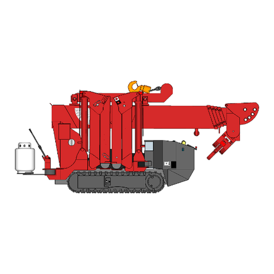
- Page 1 OPERATOR’S REFERENCE GUIDE 090-/200-SERIES Use this Guide with the Following SPYDERCRANE Models: URW094 URW095 URW095S URW205 URW205S URW295 Published by Smiley Lifting Solutions, Training Division May, 2020...
-
Page 2: Table Of Contents
This Operator’s Reference Guide for the 090- and 200-Series SPYDERCRANEs is supplementary reference guide for operating and sustaining your SPYDERCRANE. Smiley Lifting Solutions relies on customers like you to comment on errors and provide advice on how to further develop this guide. -
Page 3: Basic Information About Your Spydercrane
Basic information about Your SPYDERCRANE URW094 Ultra-Light Lifter Single Powerplant Option 110V Battery-Electric 2-Part Hook Block URW095 Ultra-Light Lifter, Expanded Capability Powerplant Options: Gasoline/VPG Diesel 110V Battery-Electric 220V Electric (as an auxiliary) ... - Page 4 Identifying Your SPYDERCRANE by its Model Number The first six digits of your SPYDERCRANE’s model number deter- mines the overall model. The five-, six-, or seven-digit suffix of the model number explains the installed powerplants that the SPYDER- CRANE is equipped with. For example, a URW295 equipped with a gasoline/vapor-propane powerplant is called the URW295CP1URS/P, while the diesel version of the same SPYDERCRANE is the URW295C4URS.
- Page 5 Your SPYDERCRANE’s Traveling Specifications and Performance URW095, URW205, URW295 (Common) URW094 Steel-Core Rubber Steel-Core Rubber Tracks 7.13 inches x 2.9 inches x 41.3 inches (on-ground) 5.9 inches x 2.8 inches x 35.4 inches (on-ground) x 2 Tracks 588.7 square inch contact patch 208.9 square inch contact patch 3,130 PSI (Traveling) 2990 PSI (Lifting) 2,210lbs.
- Page 6 Your SPYDERCRANE’s Lifting Specifications and Performance URW094 URW095, URW205, URW295 Rated Capacity 1,990 lbs. @ 4.9 ft. Rated Capacity (095) 1,990 lbs. @ 4.5 ft. (2-Part Hook Block) Lifting Height 18.3 ft. Rated Capacity (205) 5.800 lbs. @ 4.5 ft. (4-Part Hook Block) Rated Capacity (295) 6.450 lbs.
-
Page 7: Your Spydercrane's Safeties And Operator Aids
Your SPYDERCRANE’s Safeties and Operator Aids Safeties System Description Each hydraulic cylinder used by the SPYDERCRANE (Extend Cylinders for boom telescoping and outrigger deploy- ment and the Lift Cylinder used to change the angle of the boom) is equipped with a holding valve. ... - Page 8 Your SPYDERCRANE’s Safeties and Operator Aids Audible Alarms and Warning Systems System Description The Safety Horn is used to warn bystanders and can be activated from: The Safety Horn Button in the Travel Control Group (next to the Ignition Switch). Safety Horn ...
-
Page 9: Your Spydercrane's Remote Controller
Your SPYDERCRANE’s Remote Controller Remote Controller Map Function Switch When ACTIVATED, turns OFF the remote controller. Remote E-Stop The remote controller CANNOT be turned ON until the remote e-stop is deactivated (by ro- tating the e-stop switch clockwise). Power Key/Switch 2-position switch;... -
Page 10: Quiq Charger For 110V Battery-Electric Powerplants
QuiQ Charger for 110V Battery-Electric Powerplants QuiQ Charger Status Panel AMMETER LAMPS (Bulk Charge State) Displays approximate battery charge level during the bulk charging phase (up to 60%). If FLASHING, the battery array is overheating and NOT CHARGING. ... -
Page 11: The Daily Inspection
Daily Inspection Component Check For: Sat. Unsat. Carrier Rear Storage Compartment Confirm contents and inspect the compartment for damage/corrosion Travel Control Group Damage to individual controls 1-Part Hook and Holder Security, corrosion, and damage; check Safety Latch Hydraulics/Electrical Leaks, worn/damaged wiring at turret rear Start-Up Start the SPYDERCRANE, confirm normal start-up Crane Mode... -
Page 12: Check/Replace Hydraulic Oil
Service Schedule by MODEL and POWERPLANT 094-Series Description Interval Service Product The URW094 carries 4.5 gallons of hydraulic oil in Shell Tellus 32 Check/Replace Hy- 3 months (first time) its tank. Use the sight glass to check the level and draulic Oil Every 500 hours of operation thereafter NSN:9150-01-336-6589... - Page 13 Lubrication Points of Your SPYDERCRANE 094-Series Lubrication Component Lubricant Application Boom Sections Molybdenum Grease (NLGI 1,2) Manually apply to exposed boom Boom Hinge Pin Grease Fitting Molybdenum Grease (NLGI 1,2) Grease Gun Lift Cylinder Grease Fitting (Upper) Molybdenum Grease (NLGI 1,2) Grease Gun Lift Cylinder Grease Fitting (Lower) Molybdenum Grease (NLGI 1,2)
- Page 14 Check/Replace the Hydraulic Oil Vehicle Start Condition Personnel and Time Needed Tools and Equipment Needed 090-/200-Series 1 Person Hydraulic Oil (4.5 gal for 094 and 7.14 gal for 095- and 200-Series) Travel Mode Standard PPE Hook Block (any) Installed <5 minutes ...
- Page 15 Replace the Hydraulic Line Filter Vehicle Start Condition Personnel and Time Needed Tools and Equipment Needed 090-/200-Series 1 Person New Hydraulic Line Filter Travel Mode Standard PPE 10mm Hook Block (any) Installed <5 minutes 32mm ...
- Page 16 Check/Adjust Crawler Track Tension Vehicle Start Condition Personnel and Time Needed Tools and Equipment Needed 090-/200-Series 1 Person Metric Ruler, or 10mm and 15mm gauge Travel Mode Standard PPE 32mm open-end box wrench <5 minutes ...
-
Page 17: Replace Crawler Track Drive Oil
Replace Crawler Track Drive Wheel Oil Vehicle Start Condition Personnel and Time Needed Tools and Equipment Needed 090-/200-Series 1 Person Hydraulic Oil Deployed Standard PPE 8mm Allen Wrench Hook and Boom STORED <5 minutes PFTE Tape ... -
Page 18: Check/Replace Motor Oil (Gas)
Check/Replace Motor Oil (Gas Engine) Vehicle Start Condition Personnel and Time Needed Tools and Equipment Needed 095-/200-Series 1 Person Motor Oil (1.3 quarts) (CP1, CP3) Standard PPE Travel Mode <15 minutes WARNING: You MUST leave the SPYDERCRANE OFF and allow enough time for the all of the onboard fluids to return to ambient temper- ature before performing ANY maintenance. -
Page 19: Check/Replace Motor Oil (Diesel)
Check/Replace Motor Oil and Filter (Diesel Engine) Vehicle Start Condition Personnel and Time Needed Tools and Equipment Needed 095-/200-Series 1 Person Motor Oil (2.65 quarts) (C4) Standard PPE Oil Filter Travel Mode <15 minutes ... -
Page 20: Clean/Replace Air Filter
Clean/Replace Air Filter Vehicle Start Condition Personnel and Time Needed Tools and Equipment Needed 095-/200-Series 1 Person Air Filter (Diesel) (CP1, CP3, C4) Standard PPE Travel Mode <15 minutes WARNING: You MUST leave the SPYDERCRANE OFF and allow enough time for the all of the onboard fluids to return to ambient temper- ature before performing ANY maintenance. -
Page 21: Hook And Boom Deployment/Storage Procedure
Hook and Boom Deployment Procedure Vehicle Start Condition Personnel and Time Needed Tools and Equipment Needed 090-/200-Series 1 Person None Deployed (any state) Standard PPE Hook Block (any) Installed <5 minutes NOTE: Deploying the Hook and Boom is the FIRST task you must accomplish after deploying your SPYDERCRANE’s Outriggers. 1. - Page 22 Hook and Boom Storage Procedure Vehicle Start Condition Personnel and Time Needed Tools and Equipment Needed 090-/200-Series 1 Person None Deployed (any state) Standard PPE Hook Block (any) Installed <5 minutes 1. SLEW the boom until it is in-between Outrigger #1 and the carrier front-end (Fig.1). 2.
-
Page 23: Hook Block Grounding/Un-Grounding Procedure
Hook Block Grounding Procedure Vehicle Start Condition Personnel and Time Needed Tools and Equipment Needed 090-/200-Series 1 Person None Deployed (any state) Standard PPE Hook Block (any) Installed <5 minutes 1. Deploy the SPYDERCRANE’s hook and boom, using the Deploy the Hook and Boom Procedure. 2. - Page 24 Hook Block Un-Grounding Procedure Vehicle Start Condition Personnel and Time Needed Tools and Equipment Needed 090-/200-Series 1 Person None Deployed (any state) Standard PPE Hook Block Installed but Grounded <5 minutes 1. BOOM UP until the hook block is off the ground (see Fig. 1). NOTE: If there is too much slack in the wire rope to unground the hook block using BOOM UP, also use BOOM OUT but DO NOT WINCH UP until the hook block is ungrounded.
- Page 25 Install the 1-Part Hook Block (to the Boom) Vehicle Start Condition Personnel and Time Needed Tools and Equipment Needed 095-/200-Series 1 Person 13mm wrench Deployed (any state) Standard PPE Electrical Tape Boom Deployed, No Hook Block Installed <5 minutes 8mm Spacer ...
- Page 26 Install the 2-Part Hook Block (to the Boom) Vehicle Start Condition Personnel and Time Needed Tools and Equipment Needed 094-/095-Series 1 Person 17mm wrench Deployed (any state) Standard PPE 13mm wrench Boom Deployed, No Hook Block Installed <5 minutes Electrical Tape ...
-
Page 27: Install The 1-Part Hook Block (Boom)
Install the 4-Part Hook Block Vehicle Start Condition Personnel and Time Needed Tools and Equipment Needed 200-Series 1 Person 13mm wrench Deployed (any state) Standard PPE 19mm wrench Boom Deployed, No Hook Block Installed <10 minutes Electrical Tape ... - Page 28 UN-Install the 1-Part Hook Block (from the Boom) Vehicle Start Condition Personnel and Time Needed Tools and Equipment Needed 095-/200-Series 1 Person 13mm wrench Deployed (any state) Standard PPE Electrical Tape 1-Part Hook Block Installed <5 minutes Wire Rope Spacer ...
- Page 29 UN-Install the 2-Part Hook Block (from the Boom) Vehicle Start Condition Personnel and Time Needed Tools and Equipment Needed 095-/200-Series 1 Person 13mm wrench Deployed (any state) Standard PPE Electrical Tape 1-Part Hook Block Installed <5 minutes 8mm Spacer ...
- Page 30 UN-Install the 4-Part Hook Block Vehicle Start Condition Personnel and Time Needed Tools and Equipment Needed 200-Series 1 Person 13mm wrench Deployed (any state) Standard PPE Electrical Tape 4-Part Hook Block Installed <10 minutes 8mm Spacer ...
-
Page 31: Store The Wire Rope (Primary Winch)
Store/Remove the Wire Rope (Primary Winch) Vehicle Start Condition Personnel and Time Needed Tools and Equipment Needed 090-/200-Series 1 Person Rag, heavy enough to safely handle mov- ing wire rope Deployed (any state) Standard PPE Plastic shrink-wrap, or duct tape ... -
Page 32: Reeve The Wire Rope (Primary Winch)
Install the Wire Rope (Primary Winch) Vehicle Start Condition Personnel and Time Needed Tools and Equipment Needed 090-/200-Series 1 Person None Deployed (any state) Standard PPE Boom Deployed, NO Hook Block Heavyweight , rope-handling gloves ... -
Page 33: Install The Jib
Install the Jib Vehicle Start Condition Personnel and Time Needed Tools and Equipment Needed 200-Series 2 Persons None Deployed (any state) Standard PPE Boom Deployed, NO Hook Block Installed <5 minutes Installing the Jib for use with the 1-PART HOOK BLOCK 1. - Page 34 Install the Jib (continued) Installing the 1-Part Hook to the Jib Install the Jib A2B Weight to the Jib A2B Switch, using the included carabiner. Note: the Jib A2B Weight is stored in the Storage Compartment; the Wire Rope Wedge and Wire Rope Clip are taken from the 4-Part Hook Block.
- Page 35 Readying, Enabling, and Disabling the Auxiliary Winch Vehicle Start Condition Personnel and Time Needed Tools and Equipment Needed 095-/200-Series w/Aux. Winch 2 Persons 13mm Wrench Deployed (any state) Standard PPE 17mm Wrench NO Hook Block installed <15 minutes Auxiliary Winch Boom Tip Adapter (BTA) ...
- Page 36 Readying, Enabling, and Disabling the Auxiliary Winch (continued) To Install the 1-Part Hook Block to the Auxiliary Winch NOTE: If the 1-Part Hook Block is already assembled, use OPTION A. If the 1-Part Hook Block is NOT assembled and the Wire Rope Sock- et is attached to the wire rope and stored on the Wire Rope Socket Bracket on the boom, use OPTION B.
- Page 37 Load Charts: URW094 URW094 (2-Part Hook) Stage 1 4.62 1990 1990 1990 1990 1990 NOT-MAX 1760 1760 1620 1470 1430 Stage 2 8.82 1990 1990 1990 1990 1660 1460 1270 NOT-MAX 1760 1760 1450 1300 Stage 3 12.89 1870 1860 1670 1470 1300...
-
Page 38: Load Charts: Urw095S
Load Charts: URW095 URW095 (1-Part Hook) Stage 1+2 12.83 1630 1630 1630 1630 1630 1630 1630 1630 1630 NOT-MAX 1630 1630 1630 1630 1630 1600 1100 Stage 3 17.62 1630 1630 1630 1630 1630 1630 1630 1450 1000 NOT-MAX 1630 1550 1250 1150... - Page 39 Load Charts: URW095S URW095S (1-Part Hook) Stage 1+2 12.83 1630 1630 1630 1630 1630 1630 1630 1630 1630 NOT-MAX 1630 1630 1630 1630 1630 1600 1100 Stage 3 17.62 1630 1630 1630 1630 1630 1630 1630 1450 1000 NOT-MAX 1630 1550 1250 1150...
- Page 40 Load Charts: URW205 URW205 (1-Part Hook) Stage 1+2 12.83 1630 1630 1630 1630 1630 1630 1630 1630 1630 NOT-MAX 1630 1630 1630 1630 1630 1600 1100 Stage 3 17.62 1630 1630 1630 1630 1630 1630 1630 1450 1000 NOT-MAX 1630 1550 1250 1150...
- Page 41 Load Charts: URW205S URW205S (1-Part Hook) Stage 1+2 12.83 1630 1630 1630 1630 1630 1630 1630 1630 1630 NOT-MAX 1630 1630 1630 1630 1630 1600 1100 Stage 3 17.62 1630 1630 1630 1630 1630 1630 1630 1450 1000 NOT-MAX 1630 1550 1250 1150...
- Page 42 Load Charts: URW295 URW295 (1-Part Hook) Stage 1+2 12.83 1630 1630 1630 1630 1630 1630 1630 1630 1630 NOT-MAX 1630 1630 1630 1630 1630 1600 1100 Stage 3 17.62 1630 1630 1630 1630 1630 1630 1630 1450 1000 NOT-MAX 1630 1550 1250 1150...
- Page 43 Working Range Chart: URW094 For each Boom Stage, the inside arc traces the path of the Hook Height while the outside arc de- scribes the arc of the Boom Tip (for Tip Height calculations). This chart assumes a properly deployed SPYDERCRANE with 2 inches of space in-between the crawl- ...
- Page 44 Working Range Chart: URW095S, URW205S For each Boom Stage, the inside arc traces the path of the Hook Height while the outside arc de- scribes the arc of the Boom Tip (for Tip Height calculations). This chart assumes that one of the SPYDERCRANE’s standard hook blocks has been installed (NOT ...
- Page 45 Working Range Chart: URW095, URW205, URW295 For each Boom Stage, the inside arc traces the path of the Hook Height while the outside arc de- scribes the arc of the Boom Tip (for Tip Height calculations). This chart assumes that one of the SPYDERCRANE’s standard hook blocks has been installed (NOT ...
- Page 46 Working Range Chart: Jib-Equipped URW095, URW205, URW295 Boom Stage 1-4 Boom Stage Jib Tilt Angle Jib Tilt Angle Boom An- Boom An- 0° 20° 40° 60° 0° 20° 40° 60° 78° 78° 1580 1580 1580 1580 75° 75° 1580 1580 1580 1580 70°...
- Page 47 Prohibited Zones Chart Prohibited Zones In the vast majority of cases, you can deploy your SPYDERCRANE using the Optimum Deployment Pattern, but, your 090-/200-Series SPYDERCRANE is capable of deploying its outriggers to conform to environments with tight re- strictions, or immovable obstacles; this is called using a Non-Optimum Deployment Pattern. The trade-off to using the Non-Optimum Deployment Pattern is the creation of Prohibited Zones, which are areas within the SPYDER- CRANE’s Working Radius where the boom MUST NOT BE SLEWED.
- Page 48 Prohibited Zones Chart: Optimum Deployment Angle Indicators Optimum Deployment Angle Indicators At the Deployment Pivot for your SPYDERCRANE’s outrigger, you will see a pair yellow arrow indicators. These are the Optimum Deployment Angle Indicators for pre-deploying the outriggers to their Optimum Deployment Pattern. To set your SPYDERCRANE up for its Optimum Deployment Pattern, unlock and rotate the outrigger until the two ...
- Page 49 Soft-Resetting the TPD (Code 17) Vehicle Start Condition Personnel and Time Needed Tools and Equipment Needed 095-/200-Series 1 Person None Deployed Standard PPE TPD Error Alarm <5 minutes CMU CODE 17 Major Task: Make the SPYDERCRANE safe (Fig.1).
- Page 50 Hard-Resetting the TPD (Code 17) Vehicle Start Condition Personnel and Time Needed Tools and Equipment Needed 095-/200-Series 1 Person 10mm Wrench Outriggers OFF the ground Standard PPE Phillips-head screwdriver TPD Error Alarm <5 minutes ...
- Page 51 Understanding CMU Codes: Common Codes and System Error Codes Code Definition Resolution CMU is in standby and only the travel controls can be Track Control Base has been rotated into the Storage, or Travel Setting. used. The SPYDERCRANE is in Crane Mode/Remote Control To return to Crane Control , use the Remote/Crane Toggle. (Flashing) The local crane controls are being used while the SPYDERCRANE is in Remote Control SPYDERCRANE is in Crane Mode/Crane Control To go to Remote Control, use the Remote/Crane Toggle...
- Page 52 This Operator’s Reference Guide for the 090- and 200-Series SPYDERCRANEs is supplementary reference guide for operating and sustaining your SPYDERCRANE. Smiley Lifting Solutions relies on customers like you to comment on errors and provide advice on how to further develop this guide.
Need help?
Do you have a question about the SPYDERCRANE URW094 and is the answer not in the manual?
Questions and answers