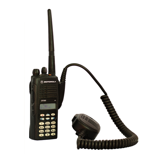
Motorola GP Series User Manual
Professional radio
Hide thumbs
Also See for GP Series:
- Detailed service manual (494 pages) ,
- Service manual (300 pages) ,
- Service information (108 pages)
Summary of Contents for Motorola GP Series
- Page 1 Professional Radio GP Series Keypad and Flex Service Information Issue: November 2004...
- Page 2 Accordingly, any copyrighted Motorola computer programs contained in the Motorola products described in this manual may not be copied or reproduced in any manner without the express written permission of Motorola. Furthermore, the purchase of Motorola...
-
Page 3: Table Of Contents
Table of Contents Chapter 1 THEORY OF OPERATION 1.0 Keypad and Flexible Connectors .................1-1 1.1 Keypad ......................1-1 1.2 Flexible Connectors..................1-1 2.0 Troubleshooting Chart ..................1-2 Chapter 2 PCB / SCHEMATICS / PARTS LISTS 1.0 Allocation of Schematics and Circuit Boards ............2-1 1.1 Flexible Connectors..................2-1 1.2 Keypad PCBs ....................2-1 2.0 PCB/Schematic Diagrams and Parts List: Flexes..........2-3... -
Page 5: Keypad And Flexible Connectors
Chapter 1 THEORY OF OPERATION Keypad and Flexible Connectors Keypad The keypad block diagram is shown in Figure 1-1. U602 is a comparator that will compare the voltage when any one of the keypad row or keypad column keys is being pressed. Therefore when a key is being pressed, it will send a message to the microprocessor through the output (KEY_INT) telling it that a key has been pressed. -
Page 6: Troubleshooting Chart
THEORY OF OPERATION Troubleshooting Chart Disconnect and Display reconnect 18-pin flex if still Off Disconnect and Keypad reconnect 40-pin flex Figure 1-2 Keypad Board Troubleshooting Chart... -
Page 7: Allocation Of Schematics And Circuit Boards
Chapter 2 PCB / SCHEMATICS / PARTS LISTS Allocation of Schematics and Circuit Boards The printed circuit boards (PCB) and schematic diagrams related to the Flexible Connectors and the Keypads are shown in the tables below: Flexible Connectors Table 2-1: Keypad /Controller Flex Flex : 8480475Z02 Flex... - Page 8 PCB / SCHEMATICS / PARTS LISTS...
-
Page 9: Pcb/Schematic Diagrams And Parts List: Flexes
PCB/Schematic Diagrams and Parts List: Flexes PCB/Schematic Diagrams and Parts List: Flexes Keypad - Controller Flex CONTROLLER KEYPAD J100 J200 EXT_MIC EXT_MIC VS_CS VS_CS SW_B+ SW_B+ <- TO KP Vddd Vddd VS_AUDSEL VS_AUDSEL Det_Aud_Snd Det_Aud_Snd Rx_Aud_Rtn Rx_Aud_Rtn Tx_Aud_Snd Tx_Aud_Snd TO CTRL -> Tx_Aud_Rtn 8480475Z02 REV A Tx_Aud_Rtn... -
Page 10: Universal Connector Flex
PCB/Schematic Diagrams and Parts List: Flexes Universal Connector Flex M400 J404 SPKR_20 J405 J403 J406 20 PIN CONN J407 SPKR_20 J408 J409 J410 J411 J412 INT_SPK+ 13 PIN UNIVERSAL CONN J413 M401 J414 INT_SPK- J415 J416 SPKR_20 EXT_SPKR+ J404 EXT_SPKR+ C402 SPKR_20 EXT_SPK-... -
Page 11: Pcb/Schematic Diagrams And Parts List: Keypad
PCB/Schematic Diagrams and Parts List: Keypad PCB/Schematic Diagrams and Parts List: Keypad PCB 8480574Z06 - Diagram R615 R614 M604 M605 M606 R617 R616 D601 D602 R620 M607 M609 R621 M608 C614 R626 R606 J602 M610 M611 M612 C642 D604 C640 C644 R601 D605 R631... - Page 12 PCB/Schematic Diagrams and Parts List: Keypad Vddd C618 C617 100pF E637 40 PIN CONNECTOR C622 100pF C610 EXT_MIC EXT_MIC J601-1 ROW3 ROW5 ROW4 M606 100pF VS_CS J601-2 VS_CS M604 M605 R614 SWITCH SWB+ J601-3 SW_B+ SWITCH SWITCH R632 C621 C620 C619 J601-4 Vddd...
-
Page 13: Pcb 8480574Z06 - Parts List
PCB/Schematic Diagrams and Parts List: Keypad PCB 8480574Z06 - Parts List Circuit Motorola Circuit Motorola Description Description Part No. Part No. Circuit Motorola Description E637 2480640Z01 C/IND BK1005HM471 BEAD R631 0662057M01 0 5% 20X40 Part No. E638 2480640Z01 C/IND BK1005HM471 BEAD... -
Page 14: Pcb 8480682Z04 - Diagrams
PCB/Schematic Diagrams and Parts List: Keypad PCB 8480682Z04 - Diagrams M601 M602 M603 R643 R629 M604 M606 M605 R631 R633 R634 R641 M607 M609 R626 R624 E616 E620 R630 R627 R606 E614 M608 E613 E618 R632 E609 Q604 R602 R603 J602 C601 M612... - Page 15 PCB/Schematic Diagrams and Parts List: Keypad ROW5 ROW3 ROW4 M601 M602 M603 SWITCH SWITCH SWITCH OUT1 OUT1 OUT1 OUT2 OUT2 OUT2 C606 100pF 40 PINS CONNECTOR SWB+ COL4 EXT_MIC EXT_MIC J601-1 VS_CS VS_CS J601-2 C607 SW_B+ ROW3 ROW4 ROW5 SWB+ J601-3 1000pF R607...
-
Page 16: Pcb 8480682Z04 - Parts List
2-10 PCB/Schematic Diagrams and Parts List: Keypad PCB 8480682Z04 - Parts List Circuit Motorola Description Part No. Circuit Motorola Description Q604 4813824A10 NPN 40V .2A GEN PURP Part No. Q605 4813824A10 NPN 40V .2A GEN PURP C601 2113743N50 100 PF 5%...


Need help?
Do you have a question about the GP Series and is the answer not in the manual?
Questions and answers