Advertisement
Quick Links
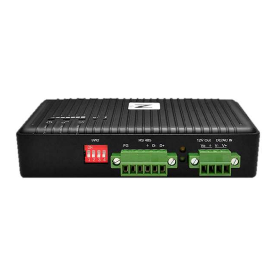
Z920K-RS485/Z920K-RS232
INTRODUCTION
Hereunder the description includes the package, and operation guides. Before start operating, please kindly read it for quick and correct
installation.
GENERRAL
Package
1.
Z920K-RS485 or RS232 Device
2.
Antenna
3.
Power Adaptor 100-240Vac /24Vdc@0.5A
4.
Micro-USB Cable
5.
Magnetic Adsorptor
6.
Din-Rail Adaptor (purchase separably)
Z920K-RS485
Sleeve Antenna
Din-Rail Adaptor (Purchase Separately)
WWW.ZOTECH.COM.TW
Getting Start Guide
x1
x1
x1
x1
x1
x1
V+
(Red
)
V- (Black)
Z920K-RS232
Micro-USB Cable
Magnetic Adsorptor
Lasted update 2019/08/30
Power Adaptor
Advertisement

Summary of Contents for ZOTECH Z920K-RS485
- Page 1 Getting Start Guide INTRODUCTION Hereunder the description includes the package, and operation guides. Before start operating, please kindly read it for quick and correct installation. GENERRAL Package Z920K-RS485 or RS232 Device Antenna Power Adaptor 100-240Vac /24Vdc@0.5A Micro-USB Cable Magnetic Adsorptor (Red Din-Rail Adaptor (purchase separably) Power Adaptor ...
- Page 2 D+/D-/GND Note: D+ (red cord)/D- (black cord) of power adaptor • Data indicators TX/Green, RX/Yellow Z920K-RS485 • RS485 D+/D- resistors and Terminal Resistor setting for impedance match. Note:“120 ohm” Terminal Res. is recommended to avoid a noise bounding. • Port Type II -RS232 DB9...
- Page 3 Data transmission: Green (10Hz blinking) stronger than -55 dBm -56 dBm ~ -65dBm Stop pairing: Green/Red 1Hz blinking simultaneously -66 dBm ~ -75dBm No light: Network unable to join or escape network -76 dBm ~ -85dBm • RSSI indication -86 dBm ~ -90dBm 3 LEDs have those 7 modes to indicate the different RSSI strength as the figure.
- Page 4 Accessory • Magnetic Adsorptor Z920K Bottom View Magnetic Adsorptor Magnetic Adsorptor Assembly • Din-Rail Adaptor Din-Rail Adaptor Assembly DIN-Rail Adaptor Combination with a Din-Rail adaptor...
- Page 5 CONSOLE UTILITY https://www.zotech.com.tw/contact-information To register on the download website for agreement to download Console Utility Please install console utility on Window PC To plug the micro-USB cable into Z920K device’s USB connector on the rear panel, and plug the other end of the USB cable into the maintenance console PC’s USB port.
- Page 6 Configuration 。 .To select Parent (Coordinator) or Child (Router) correctly to setup 。 Parent Configuration Child Node Configuration 。 To click “Module setup” for configuration 。 To click “Connect” to start up and “Load from Module” to check the current configuration...
-
Page 7: Configuration File
Configuration File • Load the configuration file into Z920K device Load Configuration • Save the present configuration file to PC Save Configuration • Recover default setting Load Default • Save the present setting as the default Save Default Mesh Network set up 。... -
Page 8: Communication Configuration
Communication Configuration The bit rate means the communication speed between Parent and Child. Please keep at the high speed 115200 bps. Don’t change any parameters on this page. Protocol Setup RS485 Modbus/RTU configuation Make sure the protocol type as “Modbus (RTU)” “Station number analysis”... - Page 9 A “Station no. list” has to be set with the sensors ID (Station number) corresponding to the short address of Child node and “Save to module”. For example: 。 Sensor Modbus ID1/ID2 are connected with Child node short address 0001 。...
- Page 10 RS232 (1-to-N) set up Parent configuration: The station number analysis needs to enable and setup the station no. table as the description on the page 7/8. Please select “Other(ASCII)” as protocol type “Start character code 1” and “Start character code 2” can be set by demand; The initial start character code1 setting is "25". “Station number start position after character code”...
- Page 11 Child configuration: “Add sender identification” has to be enabled. Child short address ID will be added in the first two bytes of the transmitted data. Note that the data logger server has to analysis the first two bytes to know where the data come from. Fixed Route Setup (Child node only) Each Child node can assign the next hopping node (Destination short address) if Fixed route “Yes”...
- Page 12 Status After the mesh network is finished, the connection status of each Parent or Child node can be checked by clicking [Status]. The MAC address, PAN ID, Radio channel number, short address, connection status, network name and RSSI (only Child node) will be shown up.
-
Page 13: Measurement Tool
Measurement Tool For start field installation, please use the measurement tool to decide the communication channel firstly, then verify communication signal level good enough. Channel Noise Scan: Click [Measurement tool] to switch device to measurement mode Mode change To select [Channel noise scan mode] and Click [Change mode] Launch Tool ... - Page 14 PER/RSSI measurement: After deciding the communication channel, the PER and RSSI have to reconfirm for all of locations of Child nodes to Parent. A reliable environment is required a lower PER (package error rate) Set one device for communication test (Sender) ...
Need help?
Do you have a question about the Z920K-RS485 and is the answer not in the manual?
Questions and answers