Table of Contents
Advertisement
Quick Links
Advertisement
Table of Contents

Summary of Contents for JMM J2 Series
- Page 1 Expandable Series Active Multifunctional Touring SOUND SYSTEM , Owner s M anual ORIGINATION AND UNIQUE 2 IN 4 OUT DSP CONTROLLER Built-in 3 way Hi-Fi Class D Amplifier Module Just plug and work,Professional and Convenient Multifunctional for kinds of Applications...
- Page 2 CAUTION The lightning flash with arrowhead symbol within an equilateral triangle is intended to alert the user to the presence of uninsulated dangerous voltage within the product's RISK OF ELECTRIC SHOCK enclosure, that may be of sufficient magnitude to constitute DO NOT OPEN a risk of electric shock to persons....
-
Page 3: Table Of Contents
CATALOGUE The main differences between J2 and J2+ systems.........1 How to set up for a J2 Active mobile system ...........2 H102 detailed specification................3 DSP18A detailed specification..............4 Parts list......................5 DSP18A Amplifier Funtions................6 Hi-Fi Class D Amplifier Module and high quality switching power Module..6 Drawing for internal structure view and cable connection .........7 How to control DSP18A by your computer..........8-11... -
Page 4: The Main Differences Between J2 And J2+ Systems
Active Multifunctional Touring SOUND SYSTEM Introduction of J2 J2 SYSTEM is showed by engineers 2 years devotion to develop,combined with domestic and international market requirement, come out of this Orinination and Unique active multifunctional touring sound system! Therefore, this user manual is suitable for both J2 and J2+ systems. The main differences between J2 and J2+ systems. -
Page 5: How To Set Up For A J2 Active Mobile System
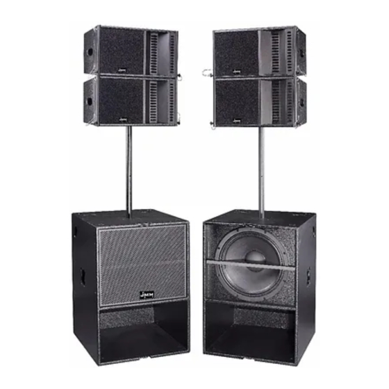
Active Multifunctional Touring SOUND SYSTEM How to set up for a J2 Active mobile system MONO(STACK)MODE A MONO(SUPPORT)MODE MONO(STACK)MODE B LINE ARRAY MODE... -
Page 6: H102 Detailed Specification
Active Multifunctional Touring SOUND SYSTEM H102 TECHNICAL SPECIFICATION Type......... Horn Loaded Mid-Hi Component........10"+2"×2+ Horn Nominal Impedance..........8Ω RMS Power Handling........350W Peak Power Handling........700W Frequency Response......55Hz-19KHz Sensitivity(1W/1M).... H102/102dB;H102+/103dB Max. SPL............130dB 120°H×10° V Dispersions........Horn throat size.......... 1"(25mm) Voice coil size..........2"(44mm) Crossover............1.5KHz Dimension HWD(mm)...... -
Page 7: Dsp18A Detailed Specification
Active Multifunctional Touring SOUND SYSTEM DSP18A TECHNICAL SPECIFICATION Type............ Active Sub Woofer Component.............18"×1 Nominal Impedance............8Ω RMS Power Handling..........600W Peak Power Handling..........1200W Frequency Response........40Hz-250Hz Sensitivity(1W/1M).....DSP18A/104dB;DSP18A+/105dB Max. SPL..............131dB Output....1×600W+2×450W Digital Power Amp Power supply..High quality Switching power supply Processor...... 32BIT, 2 In 4 Out DSP Module Dispersions..............N/A Dimension HWD(mm)........850×594×684 Shipping HWD(mm).... -
Page 8: Parts List
Active Multifunctional Touring SOUND SYSTEM Parts list Standard Accessories 4-Core Speaker Cable(Long) Power Cord for DSP18A 4-Core Speaker Cable(Short) Adjustable Tripod (use in mono Easy install and uninstallportable DJ RS485-USB cable support mode ) table and cover. Optional Accessories DSP18 loudspeaker protect cover T model trapeze (for option) 1 Ton hoist Handle lifting rod... -
Page 9: Dsp18A Amplifier Funtions
Active Multifunctional Touring SOUND SYSTEM DSP18A Amplifier Funtions SUB Input mode Convertor FULL Input FULL Link SUB Input SUB Link FULL Output(±1MID;±2HI) MODE FULL INPUT MODE 按 键弹起时 , 输入模式 为 单线全 频 输 入 Wh en the button is on , and th e input mode will be the fullrange input with both cha nnel. -
Page 10: Drawing For Internal Structure View And Cable Connection
Active Multifunctional Touring SOUND SYSTEM Drawing for internal structure view and cable connection Connetcion and switch for selection which drived by the third amplifier for Sub bass Connection for sound singal input... -
Page 11: How To Control Dsp18A By Your Computer
Active Multifunctional Touring SOUND SYSTEM How to control DSP18A by your computer 1.Open the software and select the language , the default mode is ENGLISH . Language seletive operation: Utilty->Language->ENGLISH。 2. Select in the Device option, this is suit for J2 system. Use USB connection cable to build up the connection bewteen computer and J2 system and make sure the full instalation of J2 control software and driving programein the computer. - Page 12 Active Multifunctional Touring SOUND SYSTEM How to control DSP18A by your computer Controlled parameter ① Channel selection : Default mode input 1 is Sub bass , input 2 ,Low-mid range for Full frequancy input 3 : Low range for High frequancy , Input 4: not setup. ②...
- Page 13 Active Multifunctional Touring SOUND SYSTEM How to control DSP18A by your computer ③ Optimize loudspeaker frequency response curve,After finish setting X-over and parameter (make sure the working signal range of this ourput channel) Use output channel'PEQ ,User can double click and enter into the parameter setting Menu ,and you can adjust by EQ'S active cursor on the frequency content , Active the cursor , need to click the correspondingcolorful button,And click right key on the frequenc content ,It will show as ordinate menu.
- Page 14 Active Multifunctional Touring SOUND SYSTEM How to control DSP18A by your computer ④ setup the distance of all speaker cabinets , and erase the time error of the system by adjusting the parameter of relay for each channel and make sure the Synchronous output for each channels of all cabinets.
-
Page 15: Loudspeaker Connection 1 (Mono Support Mode )
Active Multifunctional Touring SOUND SYSTEM Loudspeaker connection 1 (MONO SUPPORT MODE ) ±1 top1 ±1 top1 INPUT INPUT ±2 top2 ±2 top2 LINK LINK ±1 top1 ±1 top1 INPUT INPUT ±2 top2 ±2 top2 ±1 top1 ±1 top1 OUTPUT OUTPUT ±2 top2 ±2 top2 FULL IN... -
Page 16: Loudspeaker Connection 3 (Line Array Stack Mode )
Active Multifunctional Touring SOUND SYSTEM Loudspeaker connection 3 (LINE ARRAY STACK MODE ) INPUT INPUT LINK LINK INPUT INPUT INPUT INPUT LINK LINK INPUT ±1 top1 INPUT ±1 top1 INPUT INPUT ±2 top2 ±2 top2 LINK LINK INPUT ±1 top1/±2 top2 INPUT ±1 top1/±2 top2 INPUT INPUT... -
Page 17: Loudspeaker Connection 6 (Line Array Mode B )
Active Multifunctional Touring SOUND SYSTEM Loudspeaker connection 4 (LINE ARRAY MODE B ) ±1 top1 ±1 top1 INPUT INPUT ±2 top2 ±2 top2 LINK LINK INPUT ±1 top1/±2 top2 INPUT ±1 top1/±2 top2 TP4130 TP4130 AMPLIFIER AMPLIFIER MIXER Use 4-pole speaker cable... -
Page 18: Accessory Manual
Active Multifunctional Touring SOUND SYSTEM Accessory Manual H102 loudspeaker placed method: 1.DSP18A can be placed 2 pcs H102 inside. 2.Please place H102 Vertical always and you can put H102 into DSP18A sub hole easily (See left picuture ①). 3.Please keep H102 in the opposite side in the DSP18A, if not,H102 will collide each other while transporting Protect Cover installation method:... -
Page 19: Mono (Support) Mode Installation Metho
Active Multifunctional Touring SOUND SYSTEM MONO (SUPPORT) MODE installation metho ①Pls put the DSP18A on the ground, take out the speaker pole and insert into the hole of DSP18A, then adjust the working hight as you need. Pls see attached picture ZC-1. ②... -
Page 20: Mono(Stack) Mode Installation Method
Active Multifunctional Touring SOUND SYSTEM MONO(STACK) mode installation method ① Ground stacked the 2 subs, and install the H frame by locking the two screws. Ref.: dd-1 Load 1 top on the H frame in right position and insert the two sides lock ②... -
Page 21: Line Array Installation Method
Active Multifunctional Touring SOUND SYSTEM Line array installation method Get the first top’s front rigging point out, connect it to the front of the H frame by inserting the two ① lock pins. Insert the top’s back rigging connector to the H frame groove and adjust dispersion angle, then insert the one lock pin.
Need help?
Do you have a question about the J2 Series and is the answer not in the manual?
Questions and answers