Table of Contents
Advertisement
Quick Links
Triple Green Products
Installation Manual
IMPORTANT
Please ensure that these instructions are
read and understood before commencing
installation and start-up. Failure to
comply with these Installation
Instructions will render all warranties null
and void.
Working on the equipment
The installation, adjustment, service and
maintenance of this product must be
performed by a licensed professional
heating contractor, who is qualified and
experienced in the installation, service
and maintenance of hot water heating
boilers. There are no user serviceable
parts on the boiler or control.
Ensure main power supply to equipment,
the heating system and all external
controls has been deactivated.
Take precautions in all instances to avoid
accidental activation of power during
service work.
Improper installation, service or
maintenance can cause product/property
damage, severe personal injury, and/or
loss of life.
Advertisement
Table of Contents

Summary of Contents for Triple Green PRODUCTS CGS-277
- Page 1 Triple Green Products Installation Manual IMPORTANT Please ensure that these instructions are read and understood before commencing installation and start-up. Failure to comply with these Installation Instructions will render all warranties null and void. Working on the equipment The installation, adjustment, service and...
-
Page 2: Table Of Contents
TABLE OF CONTENTS Unloading the Stoker & Boiler ............................1 Unloading the Other Components ..........................5 Dust Collector and Components Assembly ........................5 Chimney Installation ..............................9 Combustion Air Intake ..............................11 Ash Removal System ..............................12 Condensate Return and Boiler Feed Connection (Steam System Only) ..............22 Compressed Air/Soot Blasters ............................. -
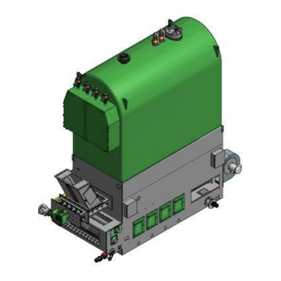
Page 3: Unloading The Stoker & Boiler
Triple Green Products Manual Installation Procedures UNLOADING THE STOKER & BOILER General notes: System arrangement may vary according to characteristic of the final project and layout of the boiler room. This manual shows the installation procedures for a typical system. Please refer to project specific drawings for final arrangement. - Page 4 Triple Green Products Manual Installation Procedures Place machinery rollers on the floor in preparation for the stoker to be placed atop the rollers. PARTS LIST ITEM PART NUMBER DESCRIPTION PROVIDED Machinery rollers IMPORTANT: Care must be taken to place the machinery rollers at each corner of the stoker. Only the corners of the stoker are designed to carry the total system weight.
- Page 5 Triple Green Products Manual Installation Procedures Once the eye bolts are removed, place the ceramic rope along the top perimeter of the stoker, approximately two inches (2”) away from the outer edge. This ceramic rope will act as a cushion between the stoker and the boiler.
- Page 6 Triple Green Products Manual Installation Procedures Use lugs to place boiler on top of the stoker - utilize spreader beam to reduce tension. PARTS LIST ITEM PART NUMBER DESCRIPTI PROVIDED Refer to serial plate Boiler Refer to serial plate Stoker...
-
Page 7: Unloading The Other Components
Triple Green Products Manual Installation Procedures UNLOADING OTHER COMPONENTS The other components include dust collector assembly consisting of dust collector and ID Fan (mounted on the frame structure), flat elbow (used for connecting the dust collector with the boiler exhaust), ash removal system (including ash removal auger and ash storage bin), chimney, walking floor components and other components. - Page 8 Triple Green Products Manual Installation Procedures PARTS LIST ITEM PART NUMBER DESCRIPTION PROVIDED TGP-0047 Dust collector frame - stand ASM-0001 Dust collector frame TGP-0045 Safety barrier type 1 TGP-0044 Chimney Y connection OEM-0069 ID Fan TGP-0046 Safety barrier type 2...
- Page 9 Triple Green Products Manual Installation Procedures 4. Place the high temperature silicone between the flat elbow and the boiler’s outlet flange. 5. Bolt the flat elbow onto the mating flange attached to the boiler using 3/8” 16UNC bolts - apply 60 ft-lbs. of torque.
- Page 10 Triple Green Products Manual Installation Procedures PARTS LIST ITEM PART NUMBER DESCRIPTION PROVIDED 3/8” 16UNC Hex Nut OEM-0072 3/8” 16UNC Hex Bolt, 1” long OEM-0071 Boiler outlet flange Using the 3/8” bolts provided connect boiler exhaust to the assembled dust collector.
-
Page 11: Chimney Installation
Triple Green Products Manual Installation Procedures CHIMNEY INSTALLATION Note: The supplied chimney will be stainless steel (SS) inside, galvanized on the outside (optional SS). Chimney size will depend on the size of the biomass system. Note: We recommend the use of “No Loss” chimney outlet. Roof penetration for the chimney is required. The chimney will be supported by the ID fan and dust collector support structure. - Page 12 Triple Green Products Manual Installation Procedures PARTS LIST ITEM PART NUMBER DESCRIPTION PROVIDED TGP-0044 Chimney Y connection Chimney OPTIONAL Chimney connection flange TGP-0048 5/16” 18UNC Hex Bolt, 1” long OEM-0073 5/16” 18UNC Hex Nut OEM-0074 Chimney flange 1. Place chimney on the center of Y connection component.
-
Page 13: Combustion Air Intake
Triple Green Products Manual Installation Procedures 3. Use provided 5/16” 18UNC bolts and nuts to attach the chimney to Y connection with connection flange. COMBUSTION AIR INTAKE Typically, the combustion air inlet is mounted at the minimum 8 ft above the ground level. The combustion air inlet is not provided with the system and needs to be provided by the installer. -
Page 14: Ash Removal System
Triple Green Products Manual Installation Procedures ASH REMOVAL SYSTEM PARTS LIST ITEM PART NUMBER DESCRIPTION PROVIDED TGP-0043 Ash Storage Bin TGP-0044 Ash Drop Box to Ash Bin Connector 6” Cross ash auger ASM-0009 TGP-0047 Cross ash auger trough cover TGP-0048... - Page 15 Triple Green Products Manual Installation Procedures PARTS LIST ITEM PART NUMBER DESCRIPTION PROVIDED OEM-0068 Bearing OEM-0014 Lovejoy coupling OEM-0013 Cross auger electric motor/gearbox TGP-0049 Cross auger drive chassis TGP-0050 Cross ash auger drive support plate 1 TGP-0051 Cross ash auger drive support plate 2...
- Page 16 Triple Green Products Manual Installation Procedures 1. Use 2 bolts to attach the bearing to cross ash auger drive support plate 1. 2. Use 4 x 5/16 18UNC Hex Bolts to attach cross ash auger drive support plate 1 with installed bearing and cross auger...
- Page 17 Triple Green Products Manual Installation Procedures 3. Bolt down cross ash auger trough to the opening on the opposite side of the stoker 4. Place the cross-ash auger in the cross-ash auger trough. Push it across the stoker and install one end of its shaft on the bearing mounted in step 1.
- Page 18 Triple Green Products Manual Installation Procedures 5. Connect the other end of the ash auger shaft to bearing mounted on connecting ash drop box.
- Page 19 Triple Green Products Manual Installation Procedures PARTS LIST ITEM PART NUMBER DESCRIPTION PROVIDED OEM-0068 Bearing ASM-0010 Connecting ash drop box OEM-0014 Lovejoy coupling 6. Use 7 x 5/16 18UNC bolts to attach the trough to connecting ash drop box...
- Page 20 Triple Green Products Manual Installation Procedures 7. Attach lovejoy coupling to the ash auger shaft. Coupling is a connector between shaft and a motor. 8. Use provided bolts to attach cross ash auger support plate 2 to auger drive chassis.
- Page 21 Triple Green Products Manual Installation Procedures 9. Connect cross auger electric motor to lovejoy coupling and use provided bolts to attach the motor to ash auger support plate 2. 10. Attach cross ash auger trough cover using provided 1/4” 20UNC self-tapping screws. Distance between the...
- Page 22 Triple Green Products Manual Installation Procedures 11. Install incline ash auger in the second opening of connecting ash auger drop box. Note: incline auger will be delivered preassembled with trough and cover 12. Make sure ash auger shaft is well connected to connecting drop box gear box.
- Page 23 Triple Green Products Manual Installation Procedures 13. Use 7 x 5/16 18UNC bolts to attach incline auger assembly to connecting ash drop box. 14. Using 8 x 5/16 18UNC bolts attach one side of the connector to incline auger drop box. The other side is equipped in rubber fitting, attach the fitting to ash storage bin inlet.
-
Page 24: Condensate Return And Boiler Feed Connection (Steam System Only)
Triple Green Products Manual Installation Procedures PARTS LIST ITEM PART NUMBER DESCRIPTION PROVIDED TGP-0043 Ash Storage Bin TGP-0044 Ash Drop Box to Ash Bin Connector CONDENSATE RETURN AND BOILER FEED CONNECTION (STEAM SYSTEM ONLY) Use appropriate piping to connect pump outlet to the boiler inlet. Refer state or provincial regulations. -
Page 25: Compressed Air/Soot Blasters
Triple Green Products Manual Installation Procedures COMPRESSED AIR/SOOT BLASTERS The system requires compressed air (100 Psig pressure) for soot blasters located on the boiler. The boiler will be shipped directly from the boiler manufacture and the soot blasters will not be mounted on the boiler but supplied loose. There are one to four zones to be connected (quantity depends on the size of the system). - Page 26 Triple Green Products Manual Installation Procedures PARTS LIST ITEM PART NUMBER DESCRIPTION PROVIDED VARIES OEM-0054 Solenoid valve 120V VARIES TGP-0042 1 1/2 Soot pipe nipples TGP-0052 Compressed air manifold 2” ball valve VARIES OEM-0069 1 1/2” union VARIES OEM-0070 1 1/2” sch80 pipe with threaded ends 6” L.
-
Page 27: Electrical/Controls
Triple Green Products Manual Installation Procedures ELECTRICAL/CONTROLS Mount the control panel inside the designated electrical room. Connect all high voltage wires between the control panel and the stoker. Connect all control wires between the control panel and the stoker. Note: Ensure the high voltage control wires are in separate conduits from each other. - Page 28 Triple Green Products Manual Installation Procedures Low Voltage Lines IMPORTANT: Low voltage lines must be run in a separate conduit from high voltage lines. Steam Pressure Sensor Line (Steam system only) IMPORTANT: Use shielded wire for steam pressure sensor wiring separate from either low or high voltage wiring. The steam pressure sensor is located on the top of the boiler and wiring must be terminated inside the control panel.
-
Page 29: Walking Floor And Components
Varies TGP-WF012 Cylinder Mounts Walking Floor (Optional) Walking Floor Specifications Boiler Model CGS-277 CGS-345 CGS-397 CGS-563 CGS-662 CGS-993 CGS-1157 CGS-1323 CGS-1654 CGS-1985 CGS-2315 CGS-2645 CGS-3075 HYD Pack HP Fuel Trough Auger Size (Horizontal) IN." Fuel Transfer Screw (Incline) IN." Total # of Wings...
Need help?
Do you have a question about the CGS-277 and is the answer not in the manual?
Questions and answers