Table of Contents
Advertisement
Quick Links
Advertisement
Table of Contents

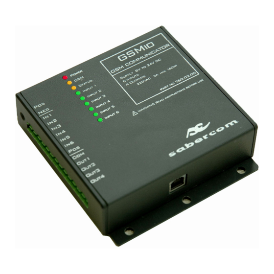
Summary of Contents for sabercom GSMio
- Page 1 GSMio Instruction manual...
-
Page 2: Table Of Contents
Index Page Introduction Product description Disclaimer and warranty Item identification Getting started What you will need Included in the package Quick start Hardware Software Connection Programming Planning Connection diagram and pin out Top cover - indication LEDs Examples Power connection Door switch Gate trigger Light switch... -
Page 3: Introduction
By linking the GSMio to any of a number of electrical devices in your life you will soon benefit from the range of features, this unique product offers. -
Page 4: What You Will Need
• Side cutters If you feel that any of the steps are outside of your ability please consult a qualified technician or electrician. You can contact Sabercom for advice or most alarm installation technicians will be able to help. For more information please consult the following sections of this manual. -
Page 5: Quick Start
Insert the SIM card in slot 1 on the underside of the GSMio unit. Connect the GSMio to a 12V DC power source. Pin 1 + and 2 - of the connector block. [Actual voltage range is 10V to 20V DC] (See “where to get 12V from”... -
Page 6: Planning
Planning: It is a good idea to plan exactly what you want to use the GSMio for and how to connect it to your home or office. Please view the following section and then the examples to get an idea of the practical application of GSMio. -
Page 7: Top Cover - Indication Leds
Input 1 to 6 – Glows when the input is on (High) Examples Power connection: In the first example the diagram for connecting the GSMio to a 12V battery to supply power is shown. (This is suitable as a temporary power source for programming or as a back up.) -
Page 8: Door Switch
The trigger wires will go to the points called COM and N/O. If you join these two points to the GSMio the output can then trigger the gate motor. -
Page 9: Gate Trigger
Light switch: The GSMio can be used to turn on a light remotely. Please note, this will usually require using mains voltage. Connections to the mains should be carried our by qualified personal only. Any errors in connection could be very dangerous, could damage the item being connected and may damage the GSMio, thus voiding the warranty. - Page 10 GSMio software and hardware. Flow The GSMio system is designed to offer a work flow that is logical and easy to follow. It has been based on the following model. Programming...
-
Page 11: Detailed Instructions
Unit ID This field is used to identify your GSMio. If selected this ID will be included in your SMS message. It is best to describe where the unit is E.g. “at home, 105 Sunny Road.” Then a complete message where an alarm has been triggered could read like this: “Alarm triggered at home, 105 Sunny Road.”... - Page 12 SIM card. This only changes the PIN number that the GSMio auto applies on start-up to activate the SIM card. If you have just received a new SIM card for your GSMio, the starter pack will include a PIN code. That is the PIN code you should enter here.
-
Page 13: View Phone Book
Clicking this icon will open a windows box to select the file you wish to load from, to the programming window. You can save a set of GSMio settings on your PC and recall those settings at any time. This means a number of GSMio units can be programmed with the same parameters, or a replaced model can be programmed the same as a previous one in a matter of seconds. - Page 14 Input and Output channel names, numbers that can control the channels as well as the send to numbers. The messages associated with the channels and the default relay status will also be included to aid with final installation of the GSMio. (This feature may not apply to your particular model) The save to file icon opens a dialog box enabling you to save a set of settings for future retrieval.
-
Page 15: Input Channel Settings
Select the GSMio Programming tab The screen is divided into two main parts. The top half contains fields relevant to the Input Channels. The lower half is for the Output channels. All the channel programming, HI and LOW messages, output defaults, time delays and numbers can be set on this screen. - Page 16 GSMio but inserting the channel names is useful to assist you with programming and set-up of the GSMio. E.g. If Channel 1 is for your alarm, type “Alarm” in the box.
- Page 17 The call box can be checked if you would prefer the GSMio to call the number instead of sending an SMS. If the box is selected for a channel High the GSMio will phone the number and allow the phone to ring three times. It will then drop the call. This only applies to one channel and to one number only.
-
Page 18: Output Channel Settings
The Output channels are relay outputs which can be switched on and off via SMS messages from your cell phone which you send to the GSMio. The fields have to be programmed in order for the GSMio to know what to do with the messages you send... - Page 19 Notify The notify box is used to select if you would like the GSMio to notify you once a request is received. E.g. if Output Channel 3 is named “Lights” and you send it an instruction to turn the lights on (pass!31) then once received the GSMio will send the following message: “Output Lights On”...
-
Page 20: Where To Get 12V
This field is used to set how long the relay will pulse for. The pulse is a change of state and is triggered by sending a 2 to the GSMio. If the Output relay is Off then it will be switched On for the length of time determined by the Pulse length, before returning to the Off state. - Page 21 1,5W to switch. Relays can be used to switch a higher voltage. In the case of GSMio 12V DC is used to switch the relays, which can in turn be used to switch a 220V AC light on or off.
-
Page 22: Sms Programming
SMS programming Via your cellphone you can do more than just control the GSMio. By using some logical codes and commands you can ask the GSMio a number of settings and if required these settings can also be updated via SMS. - Page 23 The old name will be deleted. If you would like to change it from ALARM to GEYSER type pass@opname2 GEYSER and send it to the GSMio. Default On / Off. In order to check if the default setting for the relay is on or off send pass?cond1...
-
Page 24: Quick Reference - Sms Programming
All input numbers. All the numbers that will receive messages for a particular input channel can be queried at once, but obviously not changed at once. By sending pass?in1numbers unit will answer with the list of numbers. For other channels simply change the 1 for the number of the appropriate channel. -
Page 25: Technical Specifications
Technical Specifications GSMio Supply V min Supply V max Current typ 50mA Current max 320mA Input trigger High detect Low detect Output relay Max current Relay Vmax AC Relay Vmax DC Relay current max 60 W UL/CSA rating 30Vdc / 1A -100Vdc / 0.3A... -
Page 26: Full List Of Commands
Full list of commands the formats pass four character password command query program info commands password to do action result pass turn output channel OFF pass turn output channel ON pass pulse output channel ON for xx seconds password to do command result pass... -
Page 27: Future Products
Alarm Tutorial Due to the recent features added to GSMio V2 the device can be used as an alarm system, suitable for a small business or home. By following these simple steps, you can configure the system to use it as an alarm whilst still enjoying the convenience of controlling some circuits in your premises. - Page 28 Pos and Input 3 Front door, and for the Kitchen door between Pos and Input4. Step 3 Connect the Siren to the GSMio. The siren will need to get power from the 12V supply and the negative of the siren will need to be switched through Output 2. The following diagram will help.
- Page 29 However if you would like to use the front door as your point of access allowing you to enter the home and then disable the GSMio by turning it off, set the delay to 20s. This means that from the time the front door is opened you will have 20s before the GSMio sends the messages and triggers the Automatic trigger.
-
Page 30: Troubleshooting
In the sample above the GSMio is also being used to control a Geyser as well as the electric driveway gate. The Geyser must be controlled by a separate relay as it is a high power mains circuit and a professional electrician should be used to install that part of the circuit. - Page 31 Select No, not this time then click Next Then this screen will appear: You need to specify location so click Install from a list or specific location then click next.
- Page 32 Then this screen will appear: Browse for the following file: C:\Program files\SABERCOM\GsmioSetupSoftware\CP210x\WIN Then click next. The same process has to be repeated for the Virtual Port, so repeat the steps above. Finally you will see the following screen: Your drivers are now installed.
-
Page 33: Support
Support www.sabercom.co.za For support please visit New information is available there as well as the technical support numbers and emails.
Need help?
Do you have a question about the GSMio and is the answer not in the manual?
Questions and answers