Table of Contents
Advertisement
Quick Links
Advertisement
Table of Contents

Related Manuals for VEXO PD-Monitor

Summary of Contents for VEXO PD-Monitor
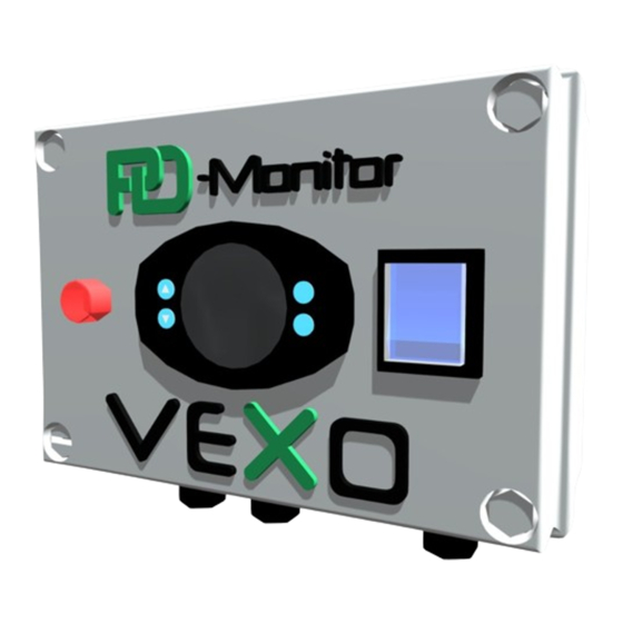
- Page 1 ® ® PD-Monitor PD-Monitor Pressure Differential Pressure Differential Monitoring Unit Monitoring Unit OPERATION & MAINTENANCE www.VEXOint.com PD-Monitor O&M Manual ® technical@VEXOint.com Last Updated - 07/03/2022 +44 (0)1767 500 150 PAGE 1...
-
Page 2: Table Of Contents
....................................WARNING – This equipment must only be used, maintained or serviced by trained competent engineers. If in any doubt please do not touch this equipment. Please contact VEXO International or your reseller for additional advice, information and guidance. www.VEXOint.com PD-Monitor O&M Manual... -
Page 3: Liability
We reserve the right to make technical changes subject to the future development of the VEXO™ product referred to in this publication. Hence no rights may be derived from technical data, descriptions and illustrations. Technical pictures, drawings and graphs do not necessarily correspond to the actual assemblies or parts as delivered. -
Page 4: Copyright
VEXO® International (UK) Ltd. Infringements are liable to prosecution and payment of compensation. We reserve the right to exercise all intellectual property rights. -
Page 5: Purpose & Use Of This Manual
All personnel must possess the relevant qualifications to carry out the required services, and be physically and psychologically capable to do so effectively. Operating instructions are transferred by VEXO® representatives, or others assigned by them, during delivery negotiations, or on demand. On-site requirements include logistics, manual... -
Page 6: Transportation, Storage & Unpacking
Emergency Stop / Emergency Off - The required EMERGENCY - STOP facility, in line with directive 2006/42EC, is present in the main power switch on the front panel. Refer to the VEXO® PD-Monitor™ Schematic, item 6 on page 9 of this document. -
Page 7: External Forces
Electrical Equipment Inspections - Regardless of the prescriptions of the property insurer / operator, it is recommended to demonstrably inspect the electrical equipment of the VEXO® PD-Monitor™ together with the heating or chilled installation at least every 12 months. Maintenance & Repair - These services may only be carried out when the VEXO PD-Monitor™... -
Page 8: Product Description
Pressure Differential Monitoring Unit Product Description - The VEXO® PD-Monitor™ is a packaged pressure differential monitoring unit. It is a fully assembled, factory tested, wall-mounted unit incorporating: • 2No 4-20 milliamp pressure transducers. • VEXO™ iX-2 12-volt Controller with RS485 MODBUS BMS connectivity - option. -
Page 9: Schematic Layout Of Various Installations
® PD-Monitor Pressure Differential Monitoring Unit Schematic Layout of Various Installations - Components List - 200mm 85mm www.VEXOint.com PD-Monitor O&M Manual ® technical@VEXOint.com Last Updated - 07/03/2022 +44 (0)1767 500 150 PAGE 9... -
Page 10: Operating Principles
Monitoring Unit Operating Principle - The VEXO PD-Monitor™ is designed to be a self-contained pressure differential monitor and ® alarm signalling device. It has a dedicated up-stream pressure transducer and down-stream pressure transducer connection to a sealed or open vented system. As system fluid passes... -
Page 11: Markings
(Basic Installation Requirements) The VEXO® PD-Monitor controller unit (item 1) is to be positioned in a dry location and fixed to a sturdy wall / frame as close as possible to the item of plant to be monitored. The ambient air temperature in which the VEXO®... - Page 12 ® PD-Monitor Pressure Differential Monitoring Unit Installation (Critical Installation Requirements) The equipment must be sited: • In a frost-free area (>5°C), protected from adverse environmental conditions. • In a well-lit area to allow for safe maintenance. • On a flat, vertical, level, solid wall or frame with clear access of 200mm all around the controller unit.
-
Page 13: Electrical Connections & Wiring Diagram
® PD-Monitor Pressure Differential Monitoring Unit Electrical Connections & Wiring Diagram - VEXO IX-2 CONTROLLER WIRING DIAGRAM ® MODBUS MODBUS Blocked Filter/Pump Fail Alarm 5A MAX Common Alarm - 5A MAX Pump 16A MAX Connections not used on PD-Monitor The provision of a power supply, (protective) ground wire connection, and line protection must be made according to local regulations and the applicable harmonised standards. -
Page 14: Commissioning
In the event of a power failure, the VEXO® iX-2 Controller will return to its last set operating mode once power has been restored. Ensure the power supply to the VEXO® PD-Monitor™ is 230V ~ 1 N PE 50Hz via a suitable Fused Spur. -
Page 15: Vexo ® Ix-2 Controller
4. ACTIVATION The VEXO® PD-Monitor™ can now be activated by pressing the Isolator Switch from the ‘Off’ position to the ‘On’ position. The VEXO® iX-2 Controller will now scroll the following... - Page 16 The VEXO PD-Monitor display will scroll a fault message as below if a fault is detected. The VEXO PD-Monitor will also initiate the visual strobe and sounder to alert the user. If connected to a BMS, the VEXO PD-Monitor will alert the user with a “Common Fault” signal. www.VEXOint.com PD-Monitor O&M Manual...
-
Page 17: Monitoring & Parameters
Pump Sense Mode). - Hold ‘Set’ (Button 4) for 5 seconds, this will store the new setting and re-boot the VEXO PD-Monitor. The new setting will be saved and the controller will return to the ® main screen. VEXO PD-Monitor Monitoring - Volt-free contacts are provided for the following conditions. -
Page 18: Electrical Checks & Inspection
Pump Hours Alarm Count Electrical Checks & Inspection - To stop electrical equipment (PD-Monitor), shut off power to the main control unit by pressing the Mains ON/OFF Power Switch (6) to the OFF position. The power supply must remail off for the entire duration of the check/inspection. -
Page 19: General Access
® PD-Monitor Pressure Differential Monitoring Unit At the end of the lifespan, or at the planned decommissioning of the equipment, please ensure: • that the PD Monitor is separated from the power supply. • that the hydraulic system connections are closed off and isolated. -
Page 20: Modbus List
® PD-Monitor Pressure Differential Monitoring Unit MODBUS List - X Variable X Variable Denomination Type Description Address Format 40001 Pressure Sensor 1 Read Word Value of Sensor 1 40002 Pressure Sensor 2 Read Word Value of Sensor 2 40003 Current... - Page 21 ® PD-Monitor Pressure Differential Monitoring Unit MODBUS List (Continued) - X Variable Data Conversion Units Range of X Variable Address 40001 Pressure Sensor 1 Decimal of Bar/PSI 40002 Pressure Sensor 2 Decimal of Bar/PSI 40003 Current Preliminary Settings 40006 Pump Relay...
-
Page 22: Declaration Of Conformity
® PD-Monitor Pressure Differential Monitoring Unit www.VEXOint.com PD-Monitor O&M Manual ® technical@VEXOint.com Last Updated - 07/03/2022 +44 (0)1767 500 150 PAGE 22... -
Page 23: Vexo ® Water Treatment Products
® PD-Monitor Pressure Differential Monitoring Unit www.VEXOint.com PD-Monitor O&M Manual ® technical@VEXOint.com Last Updated - 07/03/2022 +44 (0)1767 500 150 PAGE 23... -
Page 24: Service History
® PD-Monitor Pressure Differential Monitoring Unit Service History - www.VEXOint.com PD-Monitor O&M Manual ® technical@VEXOint.com Last Updated - 07/03/2022 +44 (0)1767 500 150 PAGE 24... - Page 25 ® PD-Monitor Pressure Differential Monitoring Unit General Notes - www.VEXOint.com PD-Monitor O&M Manual ® technical@VEXOint.com Last Updated - 07/03/2022 +44 (0)1767 500 150 PAGE 25...
- Page 26 WWW.VEXOINT.COM...
Need help?
Do you have a question about the PD-Monitor and is the answer not in the manual?
Questions and answers